 If you need a local time server, a BeagleBone Green (or BeagleBone Black) with a battery-backed real time clock and a GPS receiver with a PPS (pulse per second) output can be a cost-effective option with surprisingly good performance. Read on for detailed information about how to set up such a server.
Why You (Don’t) Need a Time Server
These are complicated instructions with a lot of steps. Before you start, think carefully about your requirements (though honestly, if you’re reading this, you are probably someone who cares deeply about microseconds, owing to either necessity or personal passion).
- If you only care about time on a human scale (i.e., being right within a smallish number of seconds), then this is overkill (by a factor of about 106).
- If you have a reliable always-on broadband Internet connection, then using public ntp servers can typically get you within a few milliseconds, with no messing about with special hardware. (Note however that residential Internet connections in the US often fail horribly at the “reliable” and “broadband” parts.)
- Without any Internet connection, a battery-backed real-time clock with a TXCO (like the DS3231 in the Chronodot) can get you time to within ±3.5ppm over a wide temperature range. (On the human scale, that’s better than a minute per year.)
- If you already built a GPS-synchronized time server using a Raspberry Pi (or some other hardware), then the approach in this article offers only an incremental improvement. (On the other hand, you may be able to scavenge parts from your old time server to build this new one.)
- If you have more budget than time and/or need a time server that someone else will support, there are lots of commercial products out there which make more sense than building your own.
- This article assumes you’re familiar with the UNIX command line in general and Debian Linux in particular, that you can build a moderately complicated software package from source, and that you know which end of a soldering iron to pick up. This isn’t a good introductory project if you’re not confident about any of those things.
If you need sub-millisecond accuracy and/or you have an isolated network (with slow, sporadic or no Internet access), having a local time server makes sense. This article will show you how to build an effective time server with cheap COTS hardware and FOSS software.
Assumptions
To get the most out of this article, please note the following:
- In all the subsequent instructions that involve shell commands, assume you need to be root unless I specifically tell you otherwise. This will spare us both the spectacle of me putting “sudo” before every single command, and inevitably screwing it up when I come to something that involves redirection or pipelines.
- Links to source, script and configuration files I’ve created all use MIME type text/plain. This means you can just click them to view the contents in your browser. To actually use any of these things, use your web browser’s native command to save the link contents (typically, something like right-click, Save As…).
- If I say to run a command as root, and you don’t understand what that command does, then don’t type the command. That admonition applies to every web page on the Internet, not just this one.
- Don’t hack hardware you can’t afford to destroy. If you connect anything that isn’t 3.3V-safe to the Beaglebone IO pins, or if you fail to observe ESD precautions, there’s a good chance you’ll end up making a moderately expensive paperweight.
Components
I used the following components for my time server:
- SeeedStudio BeagleBone Green
- Adafruit Ultimate GPS Breakout (Version 3, MTK3339 chipset)
- Macetech Chronodot TCXO RTC (Version 2.1, based on DS3231)
- Adafruit External Active GPS Antenna
- SMA to U.FL adapter cable
- BeagleBone case with access to GPIO headers
- Generic 1A 5VDC power supply with USB micro cable
You can certainly make substitutions.
Everything here should work equally well with the BeagleBone Black. (I chose the Green because it’s slightly cheaper, and I didn’t need the video output of the Black.)
The GPS receiver model isn’t critical, but it must:
- provide a 3.3V-compatible pulse-per-second output with reasonable accuracy
- have a 3.3V-compatible serial output
- accept a 3.3V or 5.0V supply voltage
- be protocol-compatible with gpsd; anything that can output NMEA sentences should be okay
Most cheap USB GPS dongles do not provide a PPS output. Without a PPS output, you will not get better than about 10ms accuracy. If you have an RS232-C GPS, do not plug it in to your BeagleBone without a level shifter. (RS232-C voltages can go from -25V to +25V, with ±15V being typical. Anything outside of 0-3.3V will fry your ‘bone.)
The BeagleBone Green (and Black) have a hardware real-time clock, but it is not battery-backed. (In other words, they’ll keep time across a reboot, but not across a power cycle.) Thus, an external battery-back real-time clock is useful. For the external RTC, there are lots of options that will work; just choose something that uses 3.3V I2C and is compatible with the Linux kernel. (Lots of RTC chips are register-compatible with the DS1307 or DS1337; these should all be OK.)
OS Installation
I like Debian-derived things, so I chose to start with the Debian 8.2 image from the BeagleBoard latest images page. That was the newest available at the time of this writing (early January 2015); if there is a newer image available when you read this, I’d encourage you to consider using it instead.
Note that Debian 8.2 uses a 4.1.x kernel. This is cool, but it means that lots of stuff has changed, and not all the documentation on the web has caught up with the changes. Be aware of this when consulting Google Tech Support.
Also remember that the Debian image in question comes up with an SSH server enabled, and uses a well-publicized username and password. Do not put it on an Internet-facing network without locking it down first. (Behind NAT is fine if you trust the users on your local network. If you want to be safe, do the initial setup on an isolated network.)
IMPORTANT: The following instructions will completely erase any data on both the built-in eMMC flash memory on your BeagleBone, and on the SD card you use. If there is any data you want to keep on either of these things, make a copy of it somewhere else before you begin.
To flash the Debian image to the eMMC flash memory on your BeagleBone:
- Download the image from the latest images page.
- Transfer the image to a 2GB or larger micro SD card (the faster, the better). (Make sure the SD card is not mounted before you begin.) Example command:
xzcat bone-debian-8.2-tester-2gb-armhf-2015-11-12-2gb.img.xz >bone-debian.img
dd if=bone-debian.img of=/dev/sdx bs=100M
Replace
/dev/sdxwith the whole-disk (not partition) device corresponding to your SD card. - After you transfer the image, your SD card should have two partitions: A tiny boot partition and a larger rootfs. Mount the boot partition, and edit the uEnv.txt to uncomment the following line:
cmdline=init=/opt/scripts/tools/eMMC/init-eMMC-flasher-v3.sh
Save the file and unmount the SD card.
- Ensure the BeagleBone power is disconnected.
- Connect the BeagleBone Ethernet jack to a network which has a DHCP server and at least one computer where you can run an SSH client.
- Place the image SD card in the BeagleBone card slot.
- Press and hold the boot switch (near the SD card slot, on the top surface of the board).
- While holding the boot switch, connect power.
- Wait for the four user LEDs (near the Ethernet jack) to light solid green then turn off.
- Release the boot switch.
In a few seconds, the user LEDs will settle into a Larson Scanner pattern (where one LED is lit at a time, bouncing back and forth in a sequence like 1,2,3,4,3,2…). This means flashing is in progress. It will take 15-30min to complete, depending on the speed of your SD card.
When the flash process is complete, the user LEDs will all go dark and stay that way. When this happens, power off your BeagleBone, remove the SD card, and re-connect power.
Initial Network Test
When your freshly-flashed BeagleBone boots up for the first time following the eMMC flash process, it should acquire a DHCP lease, and should appear on your network with the hostname “beaglebone”. Verify you can ping it.
Connect to your BeagleBone using SSH and log in as user “debian” with password “temppwd”.
User Setup
Create a new user account with all the same supplementary groups as the default “debian” user:
id -a debian
groupadd joeluser
# the following is all one long line
useradd -g joeluser -G adm,kmem,dialout,cdrom,floppy,audio,dip,video,plugdev,users,systemd-journal,netdev,i2c,xenomai,weston-launch,spi,admin -s /bin/bash -d /home/joeluser joeluser
# the above is all one long line
passwd joeluser
mkdir /home/joeluser
chown -R joeluser,joeluser /home/joeluser
Make sure you can SSH in as the new user, and that you can become root (using sudo as above) when logged in as the new user.
Delete the default “debian” user and his home directory.
Network Configuration
If you are building a network time server, you probably want to give it a static IP address. Debian 8.2 makes this harder than it ought to be. My first attempt was to change /etc/network/interfaces to something like:
auto lo
iface lo inet loopback

auto eth0
iface eth0 inet static
    address 192.168.123.45
    netmask 255.255.255.0
    gateway 192.168.123.254
When I did that and rebooted, I observed a very strange behavior: The ‘bone came up, responded to pings on the static address for a few seconds, then stopped. Further investigation revealed that it was getting a DHCP lease and re-configuring eth0 to use the dynamic address.
The culprit is a package called “connman“. It’s a cool package (I guess) and can certainly do a lot of things, but it’s overkill for a single-purpose server with a single wired Ethernet connection that has exactly one static IP. It looks like connman can be configured to do a static IP, but rather than learn how to do that, I opted to simply remove the package:
apt-get remove connman
Note that if your ‘bone has a dynamic address acquired via connman, removing the package will drop the network interface. If you are logged in via SSH, you’ll lose your connection. When I got caught by this, I just waited a few minutes to make sure everything got flushed to disk, then power-cycled the ‘bone.
Once connman is gone and you have /etc/network/interfaces set up similar to the above, you should have a static IP. There are a few other network-related tasks to be done:
- Put the correct hostname in
/etc/hostname - Edit
/etc/hoststo reflect the correct hostname and domain name. - Edit
/etc/resolv.confto point to the name server(s) on the local network.
Example resolv.conf contents:
search local.example.org
nameserver 192.168.123.1
Note that Debian 8.2 comes out of the box with IPv6 enabled. If you have native IPv6 on your network, the stack on the ‘bone will auto-configure and claim one or more IPv6 addresses. (Then again, if you’re running native IPv6, you probably want that.)
Software Updates
The system image from the latest images page will almost never be completely up to date. It’s a good idea to update the system from the network:
apt-get update
apt-get upgrade
apt-get dist-upgrade
apt-get autoremove
apt-get autoclean
Disabling Services
There’s a lot of stuff running on Debian by default that you don’t need on a time server. (I’m not bothered much by having software installed that isn’t needed. But having extra daemons constantly running is a problem, as it potentially increases jitter in the interrupt handling latency — and thus, in the time source.)
Here are some packages (with constantly running daemons) you can safely remove:
- apache2
- dnsmasq
- wpasupplicant
- nodejs (will remove a bunch of related stuff!)
(Just to be clear: None of these are bad software! All the above are actually really useful, and I use all of them in other contexts — just not on a time server.)
There’s also a thing called “jekyll“, which is some kind of web site authoring tool. It has a component that runs constantly in the background. It isn’t a Debian package, though — it’s a Ruby gem. (That’s like a package specific to the Ruby scripting language — sort of analogous to a Perl module, if that helps.) Anyway, to get rid of it:
gem uninstall jekyll
(When asked if you want to uninstall the jekyll program binary, say ‘yes’.)
Clean up the above, reboot, and check the output of ps ax to see what’s running that you don’t need.
Like it or not, systemd is a part of Debian now. So, you probably want to remove the service definitions from systemd for the things you removed above:
systemctl disable apache2.service
systemctl disable jekyll-autorun.service
systemctl disable bonescript-autorun.service
There’s also a time sync service that’s packaged with systemd. We definitely want to get rid of it, as it will try to set our system clock to a source which is less accurate than the GPS-disciplined ticker we plan to use:
systemctl stop systemd-timesyncd.service
systemctl disable systemd-timesyncd.service
That should get you to a point where systemctl status shows the system as “running” rather than “degraded” and you don’t have a bunch of things running you don’t want.
Hardware Support
There are three specific hardware interfaces we need to get working in order to answer the question “What time is it?”. These are (in order from most to least complicated): the PPS interrupt, the serial interface to the GPS receiver, and the I2C interface to the battery-backed real time clock. We’ll start by getting all the electrical connections set up, then address each of the interfaces in turn.
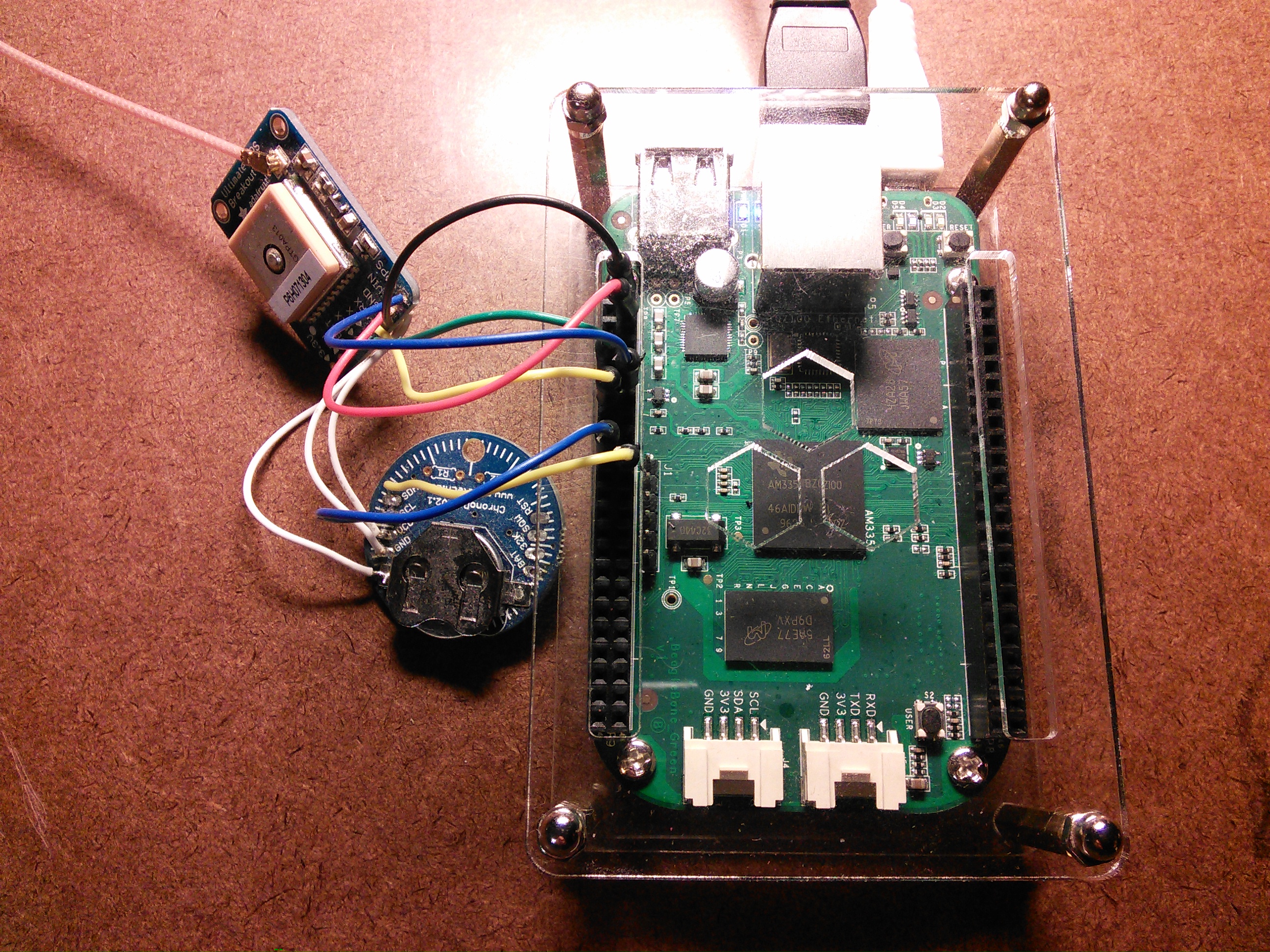
Electrical Connections
The electrical connections aren’t complicated. Here’s a simple netlist:
[table]Name,BeagleBone,GPS,RTC
Gnd,P9.2 (DGND),GND,GND
+3V3,P9.4 (VDD 3.3V),▶VIN,VCC
GPS->BBB,P9.11 (UART4_RXD),◀TX,
BBB->GPS,P9.13 (UART4_TXD),▶RX,
PPS,P9.12 (GPIO_60),◀PPS,
SCL,P9.19 (I2C2_SCL),,SCL
SDA,P9.20 (I2C2_SDA),,SDA
Battery (see below),,VBAT,BAT[/table]
Not many surprises there. The ‘bone, GPS module and Chronodot share a common ground and a common +3.3V supply. Note that the GPS TX goes to UART RX and vice-versa. Also note that the GPS module and Chronodot can share a common backup battery. Install a battery in one or the other and make the last connection in the list. (If you prefer to use a separate battery for each, do not make the last connection.)
Be somewhat careful with the PPS connection. You want to keep the length, resistance, inductance and capacitance all as low as you reasonably can, so the rising edge of the pulse will be nice and sharp. A few centimeters of wire is no big deal, but you don’t want to put it across the room.
For prototyping, I used female Schmartboard jumpers. I cut each 5″ jumper in half, then soldered the cut ends to my breakout boards. Then, the female connector end could plug in to the BeagleBone headers. That allowed me to easily connect and disconnect wires for experimentation and measurement. If you’d prefer to use a breadboard, M-F Schmartboard jumpers would do the job. For a more permanent installation, you could use a prototype cape, or a custom PCB.
Pulse Per Second
Getting PPS to work is a chore because we have to deal with device tree overlays. That’s a topic well beyond the scope of this article. In short, device tree overlays let you modify the device tree loaded at boot time, and do so at run time without building a new kernel or rebooting. The Adafruit Introduction to the BeagleBone Black Device Tree is a great place to start learning about it. For more details, try Derek Molloy’s Exploring BeagleBone textbook.
“Cape” is a term used to describe a peripheral board for the BeagleBone which stacks on the P8 and P9 headers. By default, the Debian image loads a device tree overlay at boot time called the “universal cape overlay”. This is a clever overlay which lets you do common UART, I2C and GPIO operations from user space without having to create or load custom overlays.
Unfortunately, the universal cape overlay doesn’t provide a way to connect a GPIO pin to the kernel PPS driver (or if it does, I haven’t figured it out). Worse, the universal cape overlay claims all the GPIO pins (and at most one overlay can “own” a given pin). Thus, if we wish to manage a single GPIO using our own overlay, we can’t also use the universal cape overlay.
To prevent the universal cape overlay being loaded at boot time, edit /boot/uEnv.txt and change the line that looks like:
cmdline=coherent_pool=1M quiet cape_universal=enable
to the following:
cmdline=coherent_pool=1M quiet
Once the edit is done, reboot and cat the contents of the /sys/devices/platform/bone_capemgr/slots file. It should look like this:
 0: PF----  -1
 1: PF----  -1
 2: PF----  -1
 3: PF----  -1
Next, we’ll need a custom overlay. The overlay has to do a number of different things:
- Reserve a GPIO lane and I/O pin for our exclusive use. (The bone_capemgr subsystem in the kernel will ensure that our overlay can’t get loaded if something else is already using the resources we need. Once our overlay is loaded, it will prevent loading of any other overlays that use these resources.)
- Tell the pinmux to tie our GPIO lane and I/O pin together. The processor on the ‘bone has more I/Os internally than it has pins (well, balls) to connect them to the outside world. The pinmux is like a switchboard that lets us pick and choose which internal I/Os to connect to the outside world.
- Configure the GPIO the way we want: Input, fast slew, internal pull-up enabled.
- Tell the kernel PPS driver to use our GPIO’s interrupt as a time source.
This is complicated, but fortunately there are tools and examples to make it easier. I started with the KiloBaser overlay generator. That gave me an overlay that accomplished all of the above except for the last bullet (making the kernel PPS driver use the GPIO). An example of how to do that I found on the Beagleboard group on Google.
For now, just download my completed NF3H-PPS-00A0.dts overlay source file (807B text). (You can certainly roll your own once things are working, if you want to do so as a learning exercise.) I have chosen to use P9.12, but that’s an arbitrary choice based mostly on making wiring easier. With suitable changes to the overlay, you could use any free GPIO.
(Aside: Apparently at some point in the past, the kernel PPS driver used one-based numbering for the GPIO bank, while everything else used zero-based numbering. For example, you’d use “gpio1_28” in the reservations, but “gpio2 28 0” in the gpios clause for the PPS driver. In the 4.x kernels, that is no longer the case; everything uses zero-based numbering. Much less confusing — unless you’re looking at examples that use the old method.)
Once you have a device tree source (.dts) file, you need to compile it to produce a device tree blob file (.dtbo) that can actually be loaded. Fortunately, Debian 8.2 comes equipped with a working version of the dtc (device tree compiler) command.
To simplify overlay development, I have created a Makefile (444B text) with the following targets:
- all (default) — compile the .dts source file to create a .dtbo file
- clean — remove the .dtbo file (from the current working directory only)
- install — copy the .dtbo file to /lib/firmware
- insert — add the overlay to the system by writing to the sysfs slots file
- remove — remove the overlay by writing to the sysfs slots file
However, it may be instructive to show the manual steps to compile, install and insert without using the Makefile. To compile:
dtc -O dtb -o NF3H-PPS-00A0.dtbo -b 0 -@ NF3H-PPS-00A0.dts
Once you have the .dtbo file, copy it to /lib/firmware .
To install, write the <part-number>:<version> to the bone_capemgr slots file:
echo NF3H-PPS:00A0 >/sys/devices/platform/bone_capemgr/slots
The above command should complete with no output. If you see an error message, look at the dmesg output for further information about the cause. In fact, even if it works, it’s a good idea to check the dmesg output. You should see something like the following:
[  926.283411] bone_capemgr bone_capemgr: part_number 'NF3H-PPS', version '00A0'
[  926.283504] bone_capemgr bone_capemgr: slot #5: override
[  926.283555] bone_capemgr bone_capemgr: Using override eeprom data at slot 5
[  926.283606] bone_capemgr bone_capemgr: slot #5: 'Override Board Name,00A0,Override Manuf,NF3H-PPS'
[  926.316560] pps pps0: new PPS source ocp:bs_pinmode_P9_12_0x27_pinm
[  926.316732] pps pps0: Registered IRQ 85 as PPS source
[  926.321978] bone_capemgr bone_capemgr: slot #5: dtbo 'NF3H-PPS-00A0.dtbo' loaded; overlay id #0
If you cat the slots file again, you should see the new cape registered:
 0: PF----  -1
 1: PF----  -1
 2: PF----  -1
 3: PF----  -1
 5: P-O-L-   0 Override Board Name,00A0,Override Manuf,NF3H-PPS
Check /proc/interrupts to see if you’re receiving pulses:
haku# grep ocp /proc/interrupts
 85:       5723  4804c000.gpio  28 Edge      ocp:bs_pinmode_P9_12_0x27_pinm
The second number (5723 in the above example) should increase once a second. Remember that most GPS receivers don’t produce pulses unless they have a 3D fix. If you don’t see pulses, make sure that your GPS is receiving clear signals from at least four satellites and that it has had enough time to compute a fix. An oscilloscope or even a logic probe can help you figure out if PPS pulses are being sent on the wire.
Another thing to check is the output of the ppstest utility (which is part of the “pps-tools” package):
apt-get install pps-tools
ppstest /dev/pps0
That should produce output similar to the following:
trying PPS source "/dev/pps0"
found PPS source "/dev/pps0"
ok, found 1 source(s), now start fetching data...
source 0 - assert 1451853226.000948102, sequence: 309 - clear  0.000000000, sequence: 0
source 0 - assert 1451853227.000956800, sequence: 310 - clear  0.000000000, sequence: 0
source 0 - assert 1451853228.000987999, sequence: 311 - clear  0.000000000, sequence: 0
The specific “assert” and “sequence” numbers you see may be different, but they should both increase from one line to the next.
If all the tests produce the expected results: Congratulations! You have PPS working. That’s the single most difficult part of process.
GPS Serial Interface
The PPS source tells us exactly when each second begins, but it doesn’t tell us which second we’re in. For that, we’ll need a serial UART to get NMEA sentences (or some other gpsd-compatible data) from the GPS receiver. This requires another device tree overlay, but fortunately it’s one that’s already provided for us as part of the Debian 8.2 image.
The overlay we’re going to use is BB-UART4-00A0.dtbo. As before, write the part number and version to the slots file, then check that the overlay was loaded:
haku# echo BB-UART4:00A0 >/sys/devices/platform/bone_capemgr/slots
haku# cat /sys/devices/platform/bone_capemgr/slots
 0: PF----  -1
 1: PF----  -1
 2: PF----  -1
 3: PF----  -1
 4: P-O-L-   0 Override Board Name,00A0,Override Manuf,NF3H-PPS
 5: P-O-L-   1 Override Board Name,00A0,Override Manuf,BB-UART4
Check the dmesg output for something like the following:
[ 1285.411989] bone_capemgr bone_capemgr: part_number 'BB-UART4', version '00A0'
[ 1285.412092] bone_capemgr bone_capemgr: slot #5: override
[ 1285.412143] bone_capemgr bone_capemgr: Using override eeprom data at slot 5
[ 1285.412195] bone_capemgr bone_capemgr: slot #5: 'Override Board Name,00A0,Override Manuf,BB-UART4'
[ 1285.436057] 481a8000.serial: ttyS4 at MMIO 0x481a8000 (irq = 189, base_baud = 3000000) is a 8250
[ 1285.441865] bone_capemgr bone_capemgr: slot #5: dtbo 'BB-UART4-00A0.dtbo' loaded; overlay id #1
Most GPS receivers will start sending a data stream immediately on power-up. You should be able to cat /dev/ttyS4 and see the output rolling by.
To interpret the data, install the packages gpsd and gpsd-clients:
apt-get install gpsd
apt-get install gpsd-clients
Unfortunately for us, the default installation uses systemd to dynamically start gpsd when we first connect to its socket. That’s a problem, because ntpd isn’t going to be using the socket — it’ll be using shared memory instead. That means systemd won’t detect that someone wants to use gpsd, thus gpsd won’t start, thus the shared memory region in question will never get created. Let’s fix this. First steps: Tell systemd to stop looking at the gpsd socket, and stop gpsd if it’s running:
systemctl disable gpsd.socket
systemctl stop gpsd.service
Next, configure gpsd by modifying the contents of /etc/default/gpsd:
START_DAEMON="true"
USBAUTO="false"
DEVICES="/dev/ttyS4"
GPSD_OPTIONS="-n"
(The -n option tells gpsd to talk to the GPS receiver right away, rather than waiting for a client to connect.)
Finally, edit the service definition in /lib/systemd/system/gpsd.service. We want to comment out the “Requires” and “Also” lines referring to gpsd.socket, and add a new “WantedBy” line for multi-user.target. The resulting file should look like this:
[Unit]
Description=GPS (Global Positioning System) Daemon
#Requires=gpsd.socket

[Service]
EnvironmentFile=-/etc/default/gpsd
ExecStart=/usr/sbin/gpsd -N $GPSD_OPTIONS $DEVICES

[Install]
#Also=gpsd.socket
WantedBy=multi-user.target
After that, run:
systemctl start gpsd.service
That should start gpsd. It should also be started automatically at boot time (when systemd tries to launch “multi-user.target”). Try running the cgps command; it should show you a display with reasonable time, latitude and longitude values, and a status of “3D FIX”. Press ‘q’ to quit.
Battery-Backed Real Time Clock
The I2C battery-backed real time clock module is the simplest hardware to interface. The I2C bus seems to work out of the box, no messing about with device tree overlays required.
First, make sure the clock is connected properly and that the I2C bus is working:
apt-get install i2c-tools
i2cdetect -r -y 2
You should see a device listed at I2C address 0x68:
     0  1  2  3  4  5  6  7  8  9  a  b  c  d  e  f
00:          -- -- -- -- -- -- -- -- -- -- -- -- --
10: -- -- -- -- -- -- -- -- -- -- -- -- -- -- -- --
20: -- -- -- -- -- -- -- -- -- -- -- -- -- -- -- --
30: -- -- -- -- -- -- -- -- -- -- -- -- -- -- -- --
40: -- -- -- -- -- -- -- -- -- -- -- -- -- -- -- --
50: -- -- -- -- UU UU UU UU -- -- -- -- -- -- -- --
60: -- -- -- -- -- -- -- -- 68 -- -- -- -- -- -- --
70: -- -- -- -- -- -- -- --
If that looks good, the next step is to tell the kernel about the new realtime clock:
echo ds3231 0x68 >/sys/class/i2c-adapter/i2c-2/new_device
That command should complete with no errors. Check the dmesg output; you should see something like the following:
[ 9799.869765] rtc-ds1307 2-0068: rtc core: registered ds3231 as rtc1
[ 9799.869992] i2c i2c-2: new_device: Instantiated device ds3231 at 0x68
You can check the time stored in your RTC as follows:
hwclock -r -f /dev/rtc1
If this is the first time you’ve used the RTC, or if you had to change the battery, it may have a wildly incorrect value. To set it, first set the system time (in any of the various ways there are to do that), then write the system time to the hardware clock:
hwclock -w -f /dev/rtc1
NTP Daemon Setup
Building from Source
Unfortunately, at the time of this writing, the ntpd package from the default Debian repository does not seem to have working PPS support. That’s not a big problem; we’ll just build our own from the latest sources. (It’s up to you whether you go with the production or development branch. I opted for the development version — 4.3.88 — but either should work.)
First, remove the ntp package if it’s installed, then install the libcap-dev package. (The latter is for POSIX 1003.1e capabilities, and is used to allow ntpd to set the clock without needing full root privileges at all times. It has nothing to do with the libpcap packet capture libraries.) Example commands:
apt-get remove ntp
apt-get install libcap-dev
The build process can and probably should be done as a normal user; you do not need to be root for this next part. Download the source from the NTP.org downloads page and unpack it in a directory of your choosing. Configure and build as follows:
cd ntp-dev-4.3.88 # or wherever you extracted the source
./configure --enable-linuxcaps --with-NMEA --with-ATOM
make
Note that the configure and make steps will each take a few minutes. When the build is done, you can “make install” as root.
Configuring NTPD
The basic problem we’re trying to solve is that we have two time sources (the stream of NMEA sentences coming over the serial port from the GPS module, and the PPS pulses). Neither one is sufficient, on its own, to give us an accurate idea of the time. The PPS pulses tell us very precisely when each second begins, but they provide no information about which second it is. The GPS data stream tells us the full time and date, but there’s huge variability in terms of when that information arrives. If the GPS module is sending optional sentences during some but not all of the updates (which it typically is), then we’re lucky to get within 100ms (a tenth of a second) from the serial data alone.
The solution is to tell ntpd to use the GPS and PPS data together. The serial stream tells us which second it is, and the PPS source tells us when that second starts. You can download my complete /etc/ntp.conf file (2.3KB text) for comparison (though to use it, you will at least need to edit the “restrict” line to change 192.168.12.0/24 to your local subnet).
The configuration isn’t too different from a bog-standard ntpd config. Most of the stuff to do with peers and access limits and drift files and such is the same as always. There are two clauses that are specific to this setup. First, using gpsd shared memory as a time source:
server 127.127.28.0 minpoll 4 maxpoll 4 prefer
fudge 127.127.28.0 time1 0.535 refid GPS
This requires some explanation: In the ntpd configuration, server IP addresses on the loopback (127.x.y.z) network which start with “127.127” are special. They tell ntpd that the server in question is not actually a network peer, but rather some kind of local device that can be used as a time source. The third number (y in 127.127.y.z) specifies which driver to use. (Supported drivers and the number corresponding to each can be found on the Reference Clock List page.) The meaning of the fourth number (z in 127.127.y.z) is driver-specific.
Driver 28 is the shared memory driver.
The “prefer” keyword is there because the documentation for the PPS driver (see below) specifies that the source of second numbering to be used with the top-of-second pulses must be marked as a preferred source.
The “fudge” line for the shared memory time source does two useful things. First, it specifies that the time from this source is offset, on average, 535ms from the true time. This value does not have to be exact, but we need the shared memory time (as adjusted with this offset) to be within plus or minus half a second of the true time for our clock to work. If it isn’t, our clock will end up wrong by some exact integer multiple of a second. Comparison to network time sources will tell you right away if you’re on the right second. The other thing the “fudge” line does is to provide a reference identifier (“GPS”) for this time source. This makes various diagnostic output easier to interpret.
The next part of the configuration is making ntpd use the PPS source as a way to know exactly when each second begins:
server 127.127.22.0 minpoll 4 maxpoll 4
fudge 127.127.22.0 time1 0.000 flag3 1 refid PPS
This is quite similar to the previous section, except here we use driver 22 (the PPS Clock Discipline). Note that we do not use the “prefer” keyword here.
The last octet of the address (the 0 in 127.127.22.0) is the number portion of the pps device file (so 0 is /dev/pps0, 1 is /dev/pps1 and so on). There’s a potential for confusion here, since both the PPS overlay and gpsd create PPS sources, and the device numbering depends on the order in which things happen. In the next section, we will set things up to ensure that the overlays are loaded before gpsd is run, so the hardware PPS source will always be /dev/pps0. For now, use the dmesg output and/or ppstest to verify you have the right device.
The “fudge” line sets the offest to zero (meaning the rising edge of the pulse defines the exact start of the second), and sets the reference ID. The “flag3 1” (according to the documentation) enables the kernel PPS discipline. I’m not sure what that is or whether it’s a good idea…
Making it Happen at Boot Time
At this point, you should have a working time server, but there are a lot of manual steps required to start it: loading two device tree overlays, configuring the driver for the battery-backed real time clock, setting the initial value of the system clock from the battery-backed RTC, and starting ntpd. Obviously, our time server would be a lot more useful if all these things happened at boot time. (The careful reader will note that gpsd has to be started at boot time, but that we took care of that already.)
Loading Device Tree Overlays at Boot Time
Since we’re dealing with hardware that’s going to remain connected all the time, it’s tempting to ask the bootloader to load the device tree overlays we need (by editing /boot/uEnv.txt and adding a cape_enable= line.
Indeed, for the UART this works as expected. For the PPS overlay it fails, I suspect because the kernel modules required (pps_ldisc and pps_gpio) aren’t available that early in the boot process. It might be possible to fix this (by building a custom kernel, or by modifying the initrd image), but fortunately there’s a much easier way: add a line to /etc/default/capemgr like the following:
CAPE=NF3H-PPS:00A0,BB-UART4:00A0
(Note that the comment in that file about it being sourced from /etc/init.d/capemgr.sh is a gigantic lie. It is sourced, but from /lib/systemd/system/capemgr.service. The relative order of the PPS and UART overlays doesn’t matter, as they neither depend on nor conflict with one another.)
Reboot and test. You should observe (via dmesg) that both overlays are loaded. The PPS device file associated with the GPIO pin should be /dev/pps0, while the GPSD ticker should be /dev/pps1. (This is because the PPS overlay is loaded before gpsd is started, and the system numbers the devices starting at zero in the order they are registered.) You should see reasonable time and location output in cgps.
Handling the RTC
As mentioned earlier, the ‘bone has its own built-in RTC (which does not have a backup battery). The system time is set from this built-in RTC quite early in the boot process:
[    3.529907] omap_rtc 44e3e000.rtc: already running
[    3.530379] omap_rtc 44e3e000.rtc: rtc core: registered 44e3e000.rtc as rtc0
  ...
[    3.965462] omap_rtc 44e3e000.rtc: setting system clock to 2016-01-11 22:00:41 UTC (1452549641)
Short of building a new kernel and changing CONFIG_RTC_HCTOSYS_DEVICE, I don’t know of any way to stop this happening. However, it’s reasonably easy to set up the external RTC and use it to set the system clock shortly after boot time. To do so, we first need a script (or other program) to load the clock driver and set the clock. I chose to create a SystemV-init-style script, though a simpler approach would be fine too. My RTC script: /etc/init.d/nf3h-rtc (762B text)
Note: the nf3h-rtc script linked above was buggy prior to 2016 April 15. I had forgotten to specify the device on the hwclock command line, and it was defaulting to the built-in clock instead of using the external one. If your copy of the script is not 762 bytes and/or does not contain the command “hwclock -f “$DEV” –hctosys” then please update.
Power-cycle the ‘bone and (without manually loading the RTC driver first), running the script. If you’re using my example:
/etc/init.d/nf3h-rtc start
Verify that the script loads the driver and that it sets the system clock from the hardware RTC. (Remember that you have to actually power-cycle the ‘bone as opposed to rebooting or resetting, if you want to confirm that the wall time is wrong before you run the script and correct after. Also remember that the battery-backed RTC won’t give you the right time unless you set it at some point.)
If that works, the next challenge is to ensure that our script is run at the right point in the boot process. We could just bung everything into /etc/rc.local and call it a day, but the Right Way to do it is to integrate with systemd, so let’s do that. Add a new service file /lib/systemd/system/nf3h-rtc.service (152B text) with contents like the following:
[Unit]
Description=NF3H Chronodot I2C Realtime Clock

[Service]
ExecStart=/etc/init.d/nf3h-rtc start
Type=oneshot

[Install]
WantedBy=multi-user.target
That’s about the simplest service unit you can have. It’s a thing that should run once and exit, when the system boots into multi-user mode. To actually have it run at boot time, we need to enable it:
systemctl enable nf3h-rtc.service
(Note that systemctl will try to be clever here and fail mightily. It’ll see that your service is invoking a script in /etc/init.d and decide to run update-rc.d to automagically make links in the various /etc/rc?.d based on the (non-existent) LSB tags in your script, just in case you decide on a whim to switch back to SysV init. So, you’ll get some warnings from update-rc.d complaining about missing LSB tags. You may safely ignore these. If they bother you, either add LSB tags to your init script, or put your script someplace else.)
Finally, power-cycle again and make sure that everything works as expected. If all is well, your ‘bone should have a system time which is very close to correct by the time you get to a shell prompt.
NTPD Launch at Boot
Finally, we need to create a systemd service to launch ntpd at boot time. Here, we don’t have to create a script. However, the service is a little more complicated, in part because we need to ensure that ntpd isn’t launched until all the device tree overlays are loaded, the system clock is set from the battery-backed RTC, and gpsd is running. (Remember that systemd will happily launch everything in the world concurrently unless you explicitly tell it that there are dependencies.)
Place a new service definition in /lib/systemd/system/ntpd.service (273B text):
[Unit]
Description=Network Time Protocol Daemon
After=nf3h-rtc.service capemgr.service gpsd.service network.target

[Service]
ExecStart=/usr/local/sbin/ntpd -p /var/run/ntpd.pid
PIDFile=/var/run/ntpd.pid
Type=forked
Restart=on-failure

[Install]
WantedBy=multi-user.target
The “After” line specifies all the things that have to finish launching before ntpd gets started. We tell ntpd to write a PID file, then tell systemd that ntpd is a traditional UNIX daemon that forks after launch, and that it should be restarted if it ever dies. (We tell systemd the PID file location so it has a way to tell if ntpd has terminated.)
Enable the new service:
systemctl enable ntpd.service
Reboot and confirm everything works as expected. If so: Congratulations, you made a clock.
Future Work
There are lots of ways this network time source could be improved, and a number of open questions and known problems. In no particular order:
- Can we improve accuracy by using TIMER4 to acquire a hardware timestamp on the rising edge of the PPS pulse?
- Would it make sense to use PTP (IEEE-1588) in addition to (or instead of) NTP?
- Would chrony be a better choice than the ntpd reference implementation?
- Why do the alternate character set (ACS) line-drawing characters used by cgps come out wrong in xterms? (They come out as letters jklmqx. Is this because xterm is trying to do UTF-8 and ignoring character set switching, perhaps due to locale?)
- It would be nice to set up some logging and graphing to measure and visualize accuracy and precision.
- The output of “ntpq -c rv” shows sync_pps but not kern. Should I be bothered by this? (The “kern” flag appears in some examples I’ve seen online, but not in the ntpq docco anywhere I can find.)
- Would it be helpful to write configuration information to the GPS module before gpsd starts? (I’m thinking specifically about things like setting the update rate and limiting the NMEA sentences sent to only those useful to gpsd.)
- What about checking and updating the GPS module firmware?
- I should build a nice enclosure and add some blinkenlights and maybe a local time and status display.
- It would be nice to build a proper cape on a custom PCB with the necessary hardware (including EEPROM for automatic ID and overlay loading) on board.
References
Also in no particular order:
- Network Time Protocol Project Home Page
- RFC5905:NTP Protocol and Algorithms Specification
- List of Reference Clock Drivers in the NTP reference implementation, in particular Type 22 (PPS) and Type 28 (SHM).
- BeagleBone Green Wiki
- Time-Nuts: Precise Time and Frequency for Amateurs
- Dan Drown’s notes on making a BeagleBone Black NTP server
- Satsignal.eu: comparison of BeagleBone Black vs. Raspberry Pi Model B as time servers
- NTP FAQ: The Kernel Discipline
- Linux kernel PPS GPIO driver: pps-gpio.c
- Google “BeagleBoard” Group thread on PPS Support from GPIO
- Adafruit Introduction to the BeagleBone Black Device Tree
- Derek Molloy: GPIOs on the BeagleBone
- Derek Molloy: Exploring BeagleBone (physical book on dead trees; worth it)
- KiloBaser interactive Device Tree Generator
- eLinux capemgr documentation
- Adafruit Ultimate GPS Breakout product page
- Globaltop PMTK Command documentation (528KB PDF)
- Globaltop PA6H GPS module datasheet (V0D, 1.2MB PDF) and Adafruit mirror (V0A, 1.4MB PDF)
- Adafruit Chronodot 2.1 product page
- Macetech Chronodot 2.0 documentation
- Maxim DS3231 datasheet (793KB PDF)
- Adafruit GPS antenna product page and datasheet (495KB PDF)
Updated 2016 Apr 15 DGH: Fixed bug in nf3h-rtc script which caused it to read time from the wrong device.
Hello!
Thanks for this write up! I have a question as i can’t seem to get your dts working on my system. When I copy my dtbo to the slots file I get this:
bone_capemgr bone_capemgr: part_number ‘NF3H-PPS’, version ’00A0′
[ 128.440246] bone_capemgr bone_capemgr: slot #4: override
[ 128.445690] bone_capemgr bone_capemgr: Using override eeprom data at slot 4
[ 128.452757] bone_capemgr bone_capemgr: slot #4: ‘Override Board Name,00A0,Override Manuf,NF3H-PPS’
[ 128.484632] bone_capemgr bone_capemgr: slot #4: dtbo ‘NF3H-PPS-00A0.dtbo’ loaded; overlay id #0
[ 128.519286] pps-gpio ocp:bs_pinmode_P9_12_0x27_pinmux: could not find pctldev for node /ocp/interrupt-controller@48200000, deferring probe
It seems the “/ocp/interrupt-controller@48200000” dir is actually spelled backwards on my system with “/ocp/48200000@interrupt-controller/
Do you know how I can fix this?
I’ve been following your example and using your overlay for the PPS. I am using basically the same hardware except it’s BeagleBone Black and no chronodot. I am also using chrony instead of ntpd. When I do this, it appears that the PPS gets put on /dev/pps1 instead of /dev/pps0. I see an odd entry in dmesg that seems suspect:
[ 15.286607] pps pps0: new PPS source serial4
[ 15.286684] pps pps0: source “/dev/ttyS4” added
Later in dmesg output I see:
[ 20.153005] pps pps1: new PPS source ocp:bs_pinmode_P9_12_0x27_pinm
[ 20.153109] pps pps1: Registered IRQ 88 as PPS source
I have verified with ppstest that I am indeed getting the PPS on /dev/pps1. I configured chrony to use that for the refclock entry for PPS. Chrony never appears to receive the PPS signal, so the time accuracy is off. For my application I chose chrony because these servers will not have internet access. I compiled it from source to get PPS support. Any ideas as to what might be wrong here? Thanks in advance.