 Finally, some progress on my AVR compass project. I’ve got a program that runs on the Adafruit Trinket and shows real compass headings, all in 3712 bytes. While it’s far from being a finished product, it’s a big step in the direction of one.
Below, I’ll give you the source code, talk about how recent compiler changes impact code size, tell you about a bug I fixed, and make a bunch of excuses for why this took so long.
This article is part of a larger series on building an AVR-based compass. You may be interested in the other articles in the series.
The Code
Here’s the source code: compass-20140825.tar.gz (43KB gzipped tarball)
If you have an Adafruit Trinket, an HMC5883L magnetometer and an Adafruit 8×8 LED matrix (and a way to connect them all together, like a breadboard), you can try it out. It shouldn’t be hard to adapt the code to other AVR microcontrollers and/or other display devices. Using a different magnetometer is possible, but harder.
If you want to see a video of the device in action, here is one: compass.m4v (1.8MB video; H.264 in .mp4 container). Windows users: If you’re having trouble playing this, I suggest VLC Media Player as a sovereign remedy to all your video playback problems. It’s free and works with minimal hassle.
GCC 4.8.2 and Code Size
In my previous article about code size, I noted a surprising result: compiling with -Os actually produced larger code than compiling with -O1 (even though the whole purpose of -Os is to optimize specifically for size). With my old test program and gcc 4.7.2, my binary size was 220 bytes bigger with -Os than with -O1.
When I upgraded to GCC 4.8.2 (because I’m lazy and that’s what the current Ubuntu releases use), I did a similar test. The results with the new compiler are more in line with what I’d expect: -Os produces the smallest binaries. With the new test code and gcc 4.8.2, my binary size was 154 bytes smaller with -Os than with -O1.
Another minor weirdness I noticed with gcc 4.7.2 was that marking constant functions with the “const” attribute resulted in larger code than marking them with the “pure” attribute (even though “const” promises everything “pure” does, plus some additional stuff). This is no longer the case with gcc 4.8.2.
In the past I’d alluded to but not provided a Perl script to help with size profiling. I’ve now cleaned up that script and included it with the sources linked above. You can run “make sizeprof” and get a nice breakdown of the code size for each function. If you’re trying to optimize your own project (AVR or not) for size, give it a try. I found it very helpful.
How to Fail at Debugging
With hindsight, the decision sucked. But that’s the benefit of hindsight. When you use it, all decisions suck. — Giles Todd
When I got the fixed-point math version working on the Raspberry Pi, I thought something along the lines of “That was the hard part! The rest is easy!”
In my personal experience, that thought pattern is always a red flag that indicates the exact opposite is actually the case. So, the first failure was the foolish optimism and the second was not immediately recognizing the personal anti-pattern involved.
Getting the AVR port built and running was, indeed, really simple. It seemed to get through the calibration as expected, but the outputs made no sense. The heading displayed would change as I rotated the sensor, and was consistent for any given position, but bore no resemblance to the actual compass heading — it would jump all over the compass rose in no sensible order I could discern.
I added some (very simple) diagnostics to the calibration process (the digits 1, 2 and 3 displayed on the LED matrix — still in the sources linked above). The results seemed consistent with the (working) Pi version.
My immediate and completely unsupported conclusion was that there was some subtle bug in the fixed-point math stuff that was dependent some platform-specific thing like byte order or integer size. (Failure number three: I didn’t investigate simple stuff first.) I wasted lots of time trying to decide if the calibration, rotation and arctangent functions were right, based on putting 16-bit binary values into 2×8 chunks of the LED matrix. (Failure four: wasting time with hard-to-read diagnostics when I had plenty of other options at my disposal, including a MicroView with a nice screen, a bare ATmega328P with a serial port and loads of memory, or hooking up an AVR Dragon to the Trinket with DebugWIRE.)
Way later than I should have, I realized that the code for reading the raw data from the HMC5883L was completely different in the (working) Pi version and the (failing) AVR version, and that the latter had undergone only rudimentary testing. I wrote it just after I got the LED matrix to work, and was just showing raw binary values with one bit = one LED. I showed it to some colleagues, and we all looked at the pretty lights and how they obviously change with magnetic field, and that was cool. But isn’t it funny — we all said to one another noddingly — the three axes don’t seem to behave as expected. Plenty of time to worry about it later. (So failure N: trying to debug the hard stuff before being sure the easy stuff is working. Failure N+1: having actually seen the problem demonstrated clearly, but realizing it only in hindsight.)
The Actual Bug
The X, Y and Z components of the raw magnetic field strength data are read from the chip as a stream of six bytes on the I2C bus. The way the I2C library works for reading is that you create a byte array, put the I2C (read) address of your device in the lowest-index byte, then call the library function (with the number of bytes to transfer — which is one for the address byte you’re sending plus whatever number you want to read; seven in our case) .
So I had an array like this:
uint8_t _buf[7];
where buf[0] is the read address of the HMC5883L, and buf[1] through buf[6] (inclusive) are the six bytes of raw X, Y and Z axis data. That part worked just fine.
The bug was when I tried to do the equivalent of this:
int16_t *val = (int16_t *)_buf;
x = val[0]; y = val[1]; z = val[2];
(The most basic — but not only — thing wrong with that is that it used bytes 0 and 1 for X instead of bytes 1 and 2, and so on.)
There are plenty of lessons here, but one of the big ones is that casting and pointer aliasing are for when you’re absolutely sure you’re right and want the compiler to just go ahead and do what you’re telling it to do. Both involve stripping away some of the protections normally provided by the software development tools. There are often safer and clearer ways to do the same things that are every bit as efficient in terms of bytes and cycles.
Delays
So, OK, that was a dumb bug and the a suboptimal path to finding it. But that doesn’t account for four months since the last update on this project.
Most of the reason for things taking so long are boring personal ones having to do with procrastinating and being easily distracted by other stuff that’s more interesting (in the short term) than a tedious debugging chore.
I did lose some time due to the Raspberry Pi not wanting to boot for a semi-interesting reason. I had the root filesystem on a MicroSD card in a MircoSD-to-SD adapter. The adapter had developed a tiny, almost-invisible crack lengthwise. It would still work fine in the various PCs and USB card readers I tried it in, but the Pi couldn’t see the storage device at all. Swapping the adapter fixed the problem, but that was hard to track down. (The sad part is, I have another Raspberry Pi Model B, and swapping cards would have immediately revealed that the problem was in the card, not the Pi. But that other Pi is busy Doing Stuff, and I didn’t want to take it out of service to do that test.)
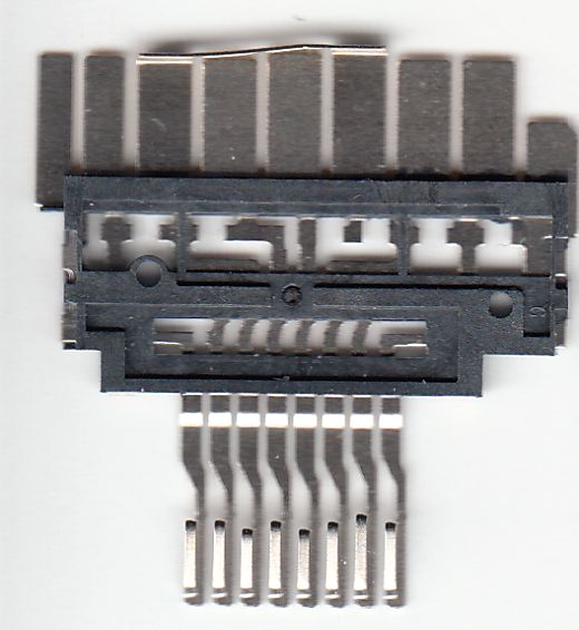 Aside: Ever wondered what the guts of a MicroSD-to-SD adapter looked like? See the picture to the right:
Next Steps
There’s still a lot to be done before this is a gadget I can stick in my car and use to find my way from place to place. Here is list of things that need to happen, in more-or-less order of priority:
- Save calibration data in EEPROM, use saved data on power-up and calibrate when requested via input pin. (Those are three things, but they have to be done together; none of them are helpful or testable without the other two.)
- Improve display feedback during calibration.
- Allow user to cancel calibration in progress and return to previously-saved values.
- Implement temperature compensation (using the built-in HMC5883L features).
- Display an error indication if the magnetometer is unreadable or if any axis is saturated.
- Display an error indication if the current (transformed) reading is too far from the unit circle.
- Improve display. The font — if you can call it that — looks awful and is inconsistent.
- Use the top two (or three) rows of the display to show fine offset from the displayed principal wind.
- Try other display options. I’ve got a 4-digit 7-segment LED backpack that could show the heading in degrees, which might be nicer. I’ve also got a small NeoPixel ring, though that’s tougher from a programming standpoint.
- Experiment with the nifty DC-to-DC converter board I got from Hong Kong. Supposedly it’ll give me clean 5VDC±30mV from a 5-28VDC input.
- Explore housing and mounting options. (I’m might try just putting the display behind one of the plastic trim pieces in the dash of my car. I think the LEDs are bright enough to show up clearly through the plastic. That would require no drilling, no cutting and be invisible when off.)
Ultimately, I might think about designing my own board and having it fabricated. (I’d still use a pre-made carrier for the HMC5883L, though — that’s way beyond my soldering skills.) That would open up some additional display options, such as two 14 or 16-segment LEDs. That’s in “maybe, someday” territory, though.
Thank you for your series of articles. I wish I had the mathematics to follow the detail rather than the general!
I am looking at an arduino application that requires a static tilt compensated compass (device is in fixed location but can be at various angles) and wonder if your sketches could be developed into this?
I have both HMC5883 and a MPU 9150. The MPU is a bit beyond me and I wonder if I can have tilt compensation on HMC?
I would like to use your idea of doing calibration/compensation at power up. As I would like to write results to EEPROM and I wonder if you have developed this further?
Regards,
Mike
Mike @1: Glad you enjoyed the articles.
My solution (with just a 3-axis magnetometer, no accelerometer) can work in any orientation, as long as the plane of rotation stays the same. (In other words, you can mount it in a car at any crazy angle and it will work, as long as you’re driving more or less along the ground and not on the wall or ceiling or something. If you change the mounting angle, you’ll need to re-calibrate.)
The MP9150 has the compass AND a 3-axis accelerometer AND a 3-axis gyroscope. With it, you can compensate for tilt that changes in real time, without having to re-calibrate. (That, and it costs about 10x what the HMc588L does.)
I have actually been working on the compass recently. Stuff I have working:
o- saving calibration to EEPROM
o- HMC5883L self-test
o- improved heading display
o- one-button calibration interface
o- display feedback during calibration
o- detection and reporting of sensor errors
Stuff I’m still working on:
o- HMC5883L temperature compensation
o- excessive tilt detection and display
o- interference detection and display
My tentative plan is to post an update sometime early to mid July. If you need something quick, email me and I’ll send you my current work-in-progress sources.