 Here’s another update in my long-running digital compass project. It’s now sufficiently feature-complete to be a potentially useful end-user product. Major improvements including saving calibration data in EEPROM, improved display, error detection and temperature compensation.
Read on after the break.
This article is part of a larger series on building an AVR-based compass. You may be interested in the other articles in the series.
Scope
This project demonstrates how to compute a compass heading using a simple three-axis magnetometer and a low-end AVR microcontroller, with an emphasis on keeping code size small.
My demonstration design uses the Adafruit Trinket, which is an extremely inexpensive board based on the ATTiny85 microcontroller. While the ATTiny85 has 8KB of program space, the Trinket bootloader leaves only about 5.5KB of this for the application — and the compass app fits with a bit of room to spare.
The approach I use can work with the sensor in any orientation, and compensates for temperature, hard-iron interference and soft-iron interference. However, it requires calibration before use, and the sensor must remain in (approximately) the same position relative to the plane of rotation between calibration and reading. (The calibration data can be save in EEPROM so it persists across power loss, and the example code does so.)
There are fancy 9-axis IMU parts that do real tilt compensation and do all the math for you, like the Bosch BNO055. If you need accelerometer and gyroscope data anyway (like in a quadcopter), that’s probably a good choice. But for some projects (like wheeled robots) a simple compass heading may be all you want, and this is a much cheaper (and lower-power, and lower parts count) way to get that.
The Build
Bill of Materials
- Adafruit Trinket (3.3V version)
- HMC5883L 3-axis magnetometer breakout board
- mini 8×8 LED matrix with I2C backpack
- SPST normally-open pushbutton switch
- printed letter grid overlay for display (print your own — see below)
- breadboard and jumpers
- power source (4-16VDC, or USB mini)
(I linked to Adafruit in the BOM because I’ve had good experiences with them, and they have most of the stuff you need in one place. No relationship other than as a happy customer. You can substitute any of the parts, though using a different display will require some code changes.)
Circuit
Nothing complicated or unexpected is going on electrically. The Trinket supplies regulated +3.3VDC to the magnetometer and display boards. A (3.3V) I2C bus connects Trinket, magnetometer and display. (I didn’t bother with pull-up resistors on the I2C bus. Not “best practices” but no problems so far.) The button sits between the Trinket PB1 pin and ground.
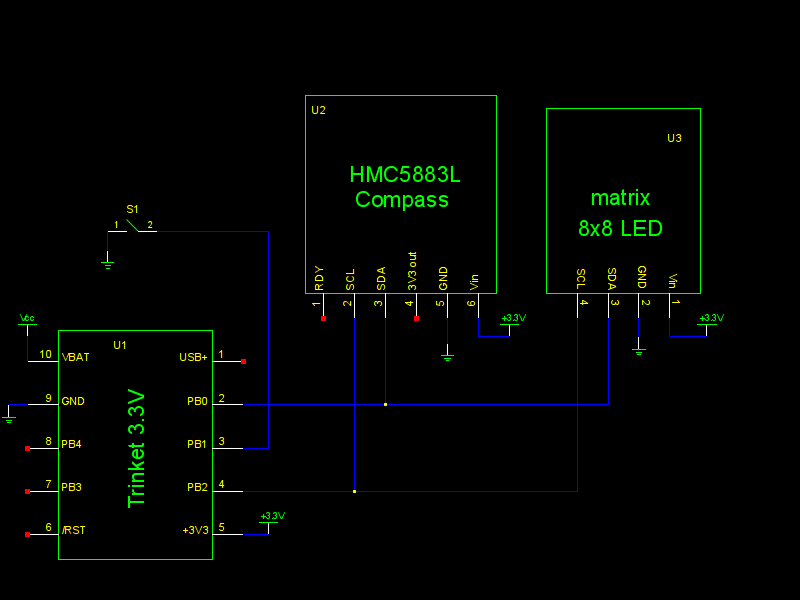 To the right is an assembly-level schematic produced using gEDA. Click the image to see a larger version. (Schematic and component files are included with the project source — see below for download.) Schematics for the individual assemblies can be found on the Adafruit website, linked from the various product pages; see the bill of materials above.
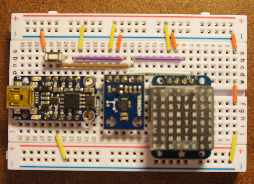 At right is a picture of the breadboard (click to see full size). Sorry for the soft focus; I didn’t have as much depth of field there as I thought. Note that there is a nearly invisible white wire going from d7 to d16 (the SCL pin on the display to the SCL pin on the HMC5883L). The three jumpers on the far right are just there to get ground from the bottom ground bus to the top. (I didn’t have one long jumper the right length, and this was more tidy than having a too-long wire flapping in the breeze.)
Display Overlay
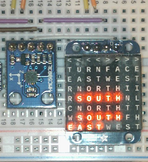
A while back, I saw a link on HackADay to Daniel Rojas’ “Micro Word Clock” project, and thought that’d be a great way to improve on the ugly display I had up to that point. (Trying to display two letters on an 8×8 grid, where one of the letters is a ‘W’? Not without some trickery.)
Using Daniel’s original SVG as a starting point, I created a similar word grid for my compass. All the necessary files are in the source download to print (or remix) your own.
The overlay you see in the pictures above is just a temporary one, printed on plain typing paper and held on with grotty transparent tape. While I’m happy with the design and layout, I plan to print a final one using transparency film and some kind of clear adhesive. That should make for much clearer text.
After playing with it for a while, I’ve come around to the opinion that the word grid display for a compass is a novelty. It’s a neat trick, but not very practical — especially in a vehicle. It’s just too small and takes too long to read. The next iteration will use one of the I2C-controlled 4-character 17-segment LED displays from Adafruit. That should be a lot faster and easier to read. (I’ve already got a Trinket library for that display from another project, too.)
Firmware
Source download: compass-20150704.tar.gz (183KB gzipped tar archive)
If for some strange reason you want one, here is a pre-compiled binary ready to flash with avrdude: compass-20150704.hex (14KB Intel hex format)
Changes
While this is not a complete change log, I wanted to mention some significant improvements from the software presented in the previous article in this series:
- Calibration data are now saved in the EEPROM. The compass will remember the calibration when you turn it off, and use the saved data on power-up.
- You can re-run the calibration process at any time by pressing the input button. There’s feedback on the display telling you what to do. You can cancel (and return to the previous calibration data) by pressing the button again while “TURN CW” is displayed.
- Error detection is greatly improved. The compass will display an error indication if the sensor is missing, saturated or fails the self-test. Interference and excessive tilt are both detected and displayed (though this part is still flaky — but it’s better than nothing).
- Temperature compensation is implemented. The HMC5883L data sheet has a detailed explanation of how it works.
This project isn’t polished or thoroughly tested, but it’s a whole lot closer than it was to being an actual gadget with practical application.
Thanks for this I’m working on something similar (using 9DoF) for use underwater! You have done a lot of the work for me. I would like to use parts of your code.
Doug,
Glad you found the project helpful. The code is released under the 3-clause BSD license (see COPYING in the source archive for details), so you are free to use it for your project — and I think it’s great if you do.