I’ve got a Kenwood TM-D710A ham radio transceiver. This handy device is a portable 50W dual-band (2m and 70cm) radio, with a built-in packet radio TNC and some native APRS features. What it does not have (unlike the new TM-D710GA model) is a built-in GPS receiver.
This is a problem that can be fixed with a surprisingly small parts budget, provided you’re up for some fine-pitch soldering. Details after the break.
The TM-D710A supports an external GPS receiver sending NMEA sentences using a three-wire serial interface signalling at RS232 levels, at any one of your choice of common port speeds. Up to this point, I had been using a Garmin Nuvi 350 with the Argent Data Systems interface cable. This worked great, but my (long-since-discontinued) GPS was having some age-related problem with battery, hardware buttons and screen. Besides which, using an external GPS plus interface and power cables for same made my installation less tidy than I liked.
I could have used the Green Light Labs GPS-710 (a plug-and-play external GPS box which sits between the control head and RF deck to get power). Heck, I could just sell the TM-D710A and buy a new TM-D710GA. But that’s no fun, and costs money.
There are a number of cheap, well-performing GPS modules on the market that are small enough to fit completely inside the control head. Why not install one of those instead?
The module I decided to try was the GP-20U7 module (PDF datasheet) sold through Sparkfun. This module was a bargain at US$16, and could do NMEA output.
IMPORTANT: The GP-20U7 uses 3.3V power and signal levels ONLY. Hooking it up to 5V or anything greater will probably kill it instantly.
Obligatory Warning You’ll Ignore
The TM-D710A is not a cheap radio, and it should go without saying that poking about the control head circuit board with a soldering pencil will comprehensively void any vestige of pity or humor the authorized service center dude or dudette will have for your plight, to say nothing of any actual warranty you might have remaining. If you’re not confident in your equipment or abilities, please stop before you break your expensive toy.
Also note that from an electrical standpoint, this is a total hack that just happens to coincidentally work on my particular radio. I’m driving the output pin of the RS-232 adapter with the GPS TX pin; with the series resistor, the impedance seems to be high enough to work and not fry anything. I’m driving (what I think is) a 5V serial input with a 3.3V signal; it works reliably for me, for now. I’ve run it for a number of hours and nothing seems to get too hot, but I haven’t done any real thermal analysis. My radio seems to “hear” OK after the mod, but I don’t have the lab equipment to test it for real, and if it’s not expressed in figures, it’s opinion.
If you’re still on board after reading all that, and if you have surface-mount technique that rises at least to the level of “really average”, you should be fine. No disclaimer, you assume all responsibility, etc.
Bench Testing
Once I had the GPS receiver module in hand, the first thing I did was to test it on the workbench using a Dangerous Prototypes Bus Pirate. (For those of you unfamiliar with the Bus Pirate, it is a USB device that speaks serial / I2C / SPI / JTAG / what have you; it’s a sovereign remedy for a wide range of “talk to my widget” problems, and one of the best bargains in the world of test equipment.) If you don’t have a Bus Pirate, you could accomplish the same thing with a regulated power supply and either a USB-to-3V3 serial dongle, or a plain old serial port and a level shifter.
First, I put the Bus Pirate into UART mode:
Bus Pirate v3b
Firmware v5.10 (r559)  Bootloader v4.4
DEVID:0x0447 REVID:0x3046 (24FJ64GA002 B8)
http://dangerousprototypes.com
HiZ>m
1. HiZ
2. 1-WIRE
3. UART
4. I2C
5. SPI
6. 2WIRE
7. 3WIRE
8. LCD
9. DIO
x. exit(without change)

(1)>3
Set serial port speed: (bps)
 1. 300
 2. 1200
 3. 2400
 4. 4800
 5. 9600
 6. 19200
 7. 38400
 8. 57600
 9. 115200
10. BRG raw value

(1)>5
Data bits and parity:
 1. 8, NONE *default
 2. 8, EVEN
 3. 8, ODD
 4. 9, NONE
(1)>1
Stop bits:
 1. 1 *default
 2. 2
(1)>1
Receive polarity:
 1. Idle 1 *default
 2. Idle 0
(1)>1
Select output type:
 1. Open drain (H=Hi-Z, L=GND)
 2. Normal (H=3.3V, L=GND)
Then, I used the ‘v’ command to show which test leads were assigned to what function:
UART>v
Pinstates:
1.(BR)	2.(RD)	3.(OR)	4.(YW)	5.(GN)	6.(BL)	7.(PU)	8.(GR)	9.(WT)	0.(Blk)
GND	3.3V	5.0V	ADC	VPU	AUX	-	TxD	-	RxD
P	P	P	I	I	I	I	I	I	I
GND	0.00V	0.00V	0.00V	0.00V	L	L	H	L	H
Note that different versions of the Bus Pirate — or even the same version sold by different vendors — can have different lead assignments. Verify your own hookup; do not blindly duplicate mine. Based on the above output, I wired it up as follows:
- Bus Pirate GND (brown wire) to GPS GND (black wire)
- Bus Pirate 3V3 (red wire) to GPS Vcc (red wire)
- Bus Pirate UART RxD (black wire) to GPS TX (white wire)
Then, I ran macro (2) (live raw UART monitor) and… nothing. Oh. The Bus Pirate power supply defaults to a safe (off) state. Maybe it’ll work better if I turn the power on.
UART>W
Power supplies ON
UART>v
Pinstates:
1.(BR)	2.(RD)	3.(OR)	4.(YW)	5.(GN)	6.(BL)	7.(PU)	8.(GR)	9.(WT)	0.(Blk)
GND	3.3V	5.0V	ADC	VPU	AUX	-	TxD	-	RxD
P	P	P	I	I	I	I	I	I	I
GND	3.28V	4.90V	0.00V	0.00V	L	L	H	L	H
That’s better! Look, data:
UART>(2)
Raw UART input
Any key to exit
$GPRMC,233526.00,A,29[redacted],N,095[redacted],W,0.182,,080117,,,D*62
$GPVTG,,T,,M,0.182,N,0.338,K,D*25
$GPGGA,233526.00,29[redacted],N,095[redacted],W,2,10,0.81,30.1,M,-24.3,M,,0000*5E
$GPGSA,A,3,16,23,03,26,22,14,31,07,27,09,,,1.47,0.81,1.23*04
$GPGSV,4,1,15,03,47,224,19,04,30,040,20,07,12,273,19,08,09,173,*7B
$GPGSV,4,2,15,09,21,316,23,14,15,120,18,16,74,056,34,22,38,205,28*79
$GPGSV,4,3,15,23,60,331,33,26,43,042,23,27,27,138,22,31,13,066,22*72
$GPGSV,4,4,15,46,56,185,30,48,37,237,,51,53,203,*4E
$GPGLL,29[redacted],N,095[redacted],W,233526.00,A,D*7F
What I learned from this test was:
- The GPS module works.
- It draws about 40ma.
- It defaults to NMEA output at 9600 baud, with about 1Hz updates.
- It is able to acquire a fix even inside my house, and even if I cover the antenna with stuff (like a thin textbook) that attenuates the signal.
- The time-to-first-fix after power-on seems to be about 30s at most.
Connection Planning
I had a GPS module that would fit in the control head and that output data in the correct format. But there were still a couple problems to be solved:
- Where could I get +3.3VDC power?
- How could I make the TM-D710A understand serial signals where mark is 0V and space is 3.3V?
Fortunately, the schematic for the TM-D710A isn’t hard to find online. (I’m not certain about the copyright status, so I won’t host it or link it here. A quick Google search will get you what you need.)
The external GPS jack is connected in a fairly obvious way to an Analog Devices ADM101E RS232 transceiver (PDF datasheet):
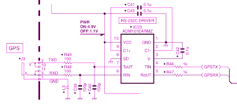
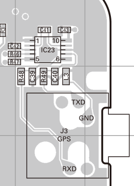
My theory was that I should be able to connect the GPS output to R47, on the side away from IC23 pin 5, and get data to the microcontroller in the TM-D710A control head. But where was that physically on the board? It turns out to be pretty easy to see:
I didn’t find any 3.3VDC power source from which I felt comfortable pulling 40ma. However, there’s a handy 5VDC pin right there on IC23 pin 10 (and one side of C43). I could always use a regulator. But first, let’s see if I’m right about the data.
Data Test
Before I really committed to anything, I needed to make sure that feeding a 3.3V serial signal in at R47 (opposite IC23 pin 5) would actually work. First, I made sure the control head was set up to accept GPS data at 9600 baud:
- Menu 602: BAUD RATE = 9600 bps
- Menu 602: INPUT = GPS
- Menu 602: OUTPUT = OFF
(Yes, I do know the difference between baud and bps. That’s just how Kenwood wrote their menus.)
Next, I powered off everything and disassembled the control head. The only tricky part here is removing the round nuts that hold the three control knobs in place on the front of the housing. I didn’t have the correct tool for that (nor am I even sure what that tool is called). However, with some care and a pair of needle-nose pliers, I was able to get things apart.
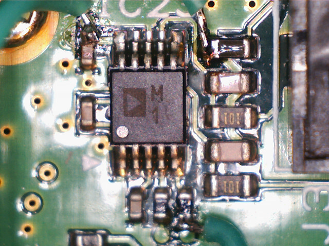
Because the point where I needed to make a connection was on the opposite side of the board from the display, I elected to solder a wire in place. (There’s no reasonable way I could hold a probe in place blindly while looking at the display to see if the test was working.) While the leads and traces on the TM-D710A control head board aren’t super-tiny, they’re not particularly big either. (The pins on IC23 are 0.5mm center-to-center.) Big clunky wire would make this harder than it needed to be. I used the 30AWG stranded silicone-insulated wire from Adafruit. I love that stuff: It’s skinny (0.8mm OD), slinky, supple, easy to strip and easy to solder.
Then, I connected the GPS module to a bench supply set to 3.3VDC (and current-limited to 100mA, just in case). I connected the GPS and bench supply ground to the TM-D710A ground with a spring-clip jumper. (There are lots of easily accessible grounds. I used the plated-through mounting hole in the corner of the board. Finally, I connected the GPS TX pin to the test lead.
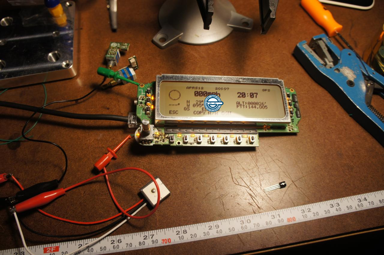
Success! The “GPS” indicator on the control head started blinking, and I had a good position and time on the “POS” page.
Power Regulation
The next problem was how to get from the 5VDC supply on the control head board to the 3.3VDC needed by the GPS module. In response to my support question about “Can I run the GP-20U7 off a 5V supply?”, Chris F. at Sparkfun said “no” (which answer I’d kind of expected), but suggested using a voltage regulator in a TO-92 package.
(Editorial aside: I bought a $16 part from Sparkfun, asked a technical question by email and got a response which was timely, correct, addressed the question I’d actually asked, and offered additional useful information. I’m impressed, and will be buying more stuff from them. I’ve made much bigger purchases from bigger vendors from whom I’ve subsequently received far worse support.)
Unfortunately, neither my parts bin nor Sparkfun had such a regulator. I ordered some STMicroelectronics L78L33ACZ units (PDF datasheet) from another vendor.
Once they arrived, it was time for another bench test. I used my bench supply (again current-limited to 100mA) to feed 5V to the regulator by itself. The multimeter showed a nice steady 3.3V output. Next, I connected GPS module to the regulator output. It stayed at 3.3V, pulling about the expected 40mA. Using the Bus Pirate, I verified the GPS was sending out the expected NMEA data stream. It was working fine.
Next, I connected the regulator to the GPS receiver with soldered connections, and bundled everything up in heat-shrink (polyolefin) tubing and Kapton tape so nothing could possibly short in the field. Another test to verify I wired it up right; all is well.
Installation
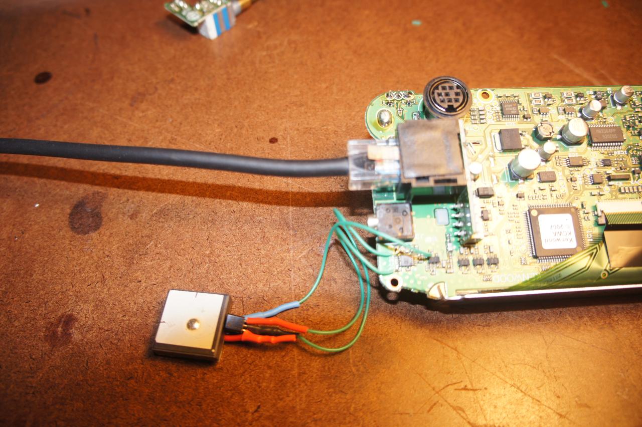 This was actually the easy part. My test wire from earlier was still attached to the data input line; I just left it in place and connected the other end to the GPS receiver TX pin. Then, I had to get 5V (from the side of C43 connected to IC23 pin 10) and ground from anywhere handy (I used the side of L23 closest to IC23).
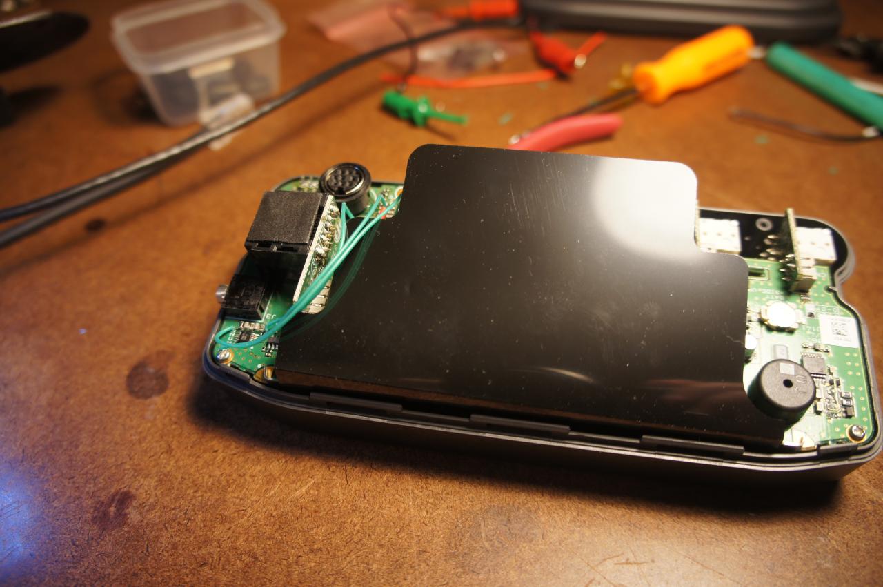
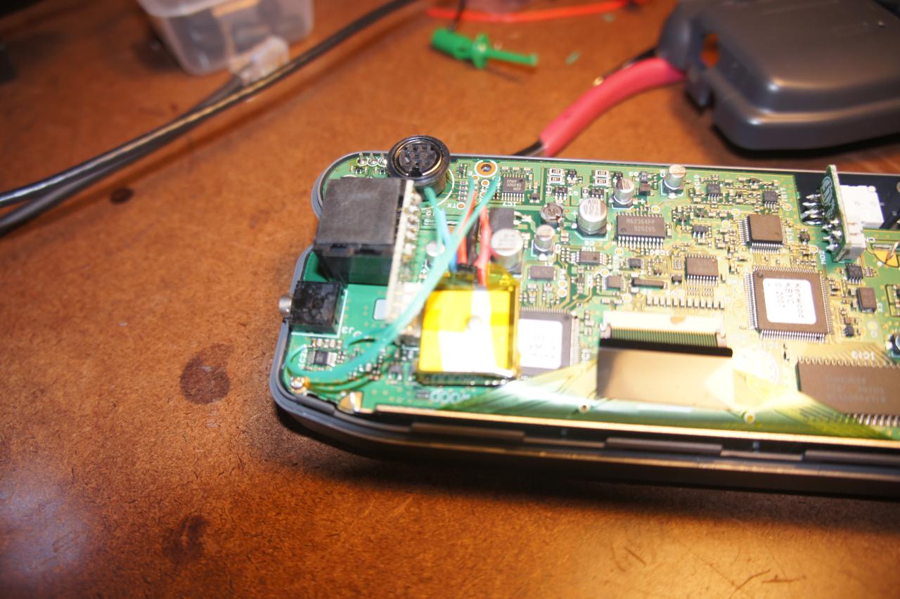 After that, it was just a matter of carefully figuring out where the receiver would be physically fit without creating interference, risking a short, causing thermal problems or physically pushing on anything delicate.
After putting it back together, it worked but it seemed to take way too long sometimes to acquire a fix. After some experimentation, I found out that the black plastic insulating sheet in the control head seemed to be radiopaque at GPS frequencies (1575.42 MHz and/or 1227.60 MHz). Leaving it out solved the problem.
I just completed this and it works great!
I was able to install the GPS with the black plastic. The plastic is most likely some sort of shielding. I placed the GPS module on top of the plastic, instead of underneath it. I also found that placing the GPS on the back cover, where you want it to sit, and using tape to hold it while you screw the cover on works really well.
The kex to this is the right tools. Adequate magnification and light is key to success. A fine tip soldering iron is worth the investment as well. I was able to use a Weller WLC100, but it was a challenge.
I used the wires from an old ball mouse, but any small gauge wire should work.
Without fail I always manage to flip the pinout for the TO-92 package on the L78L33ACZ around. So if you do this, and the GPS doesn’t seem to power up, make sure you haven’t swapped pins 1 and 3 on the voltage regulator.
73, Reid N0RC
I’m just preparing to do this mod. Can I get some feedback as to how your rigs have held up? Any Problems?
Thanks
Terry VE3IQL
No problems so far.
Caveat: My rig is currently a base station, sitting on a desk in a temperature-controlled room. A vehicle would be a much more challenging environment. However, I know of no reason why the GPS receiver would be more susceptible to problems than any other electronic component.
Thank you for the reply.
I was more concerned with the control head than the GPS receiver.
I haven’t received my GPS receiver yet, (tomorrow) but am ready to put it in. I will post my results as well.
What a great idea this is!
Thanks
Finished the project. Worked on the first setup! No problems at all setting it up with the very excellent instructions and photo’s.
Very nice setup now.
Thanks
73
did your mod and it works excelent , Biggest problem soldering on the small parts as my hands are shaking,Else realy nice mod
thanks
73 Lars Sm4IVE
Thank you for the detailed write-up.
You didn’t mention using any capacitors from input to ground or output to ground on the voltage regulator. Does it not need them as shown in the spec sheet?
I didn’t use any decoupling caps. You’re absolutely right about that being mildly naughty per the datasheet.
In my particular case (anecdata!) it seems to do OK without. YMMV. I’d be more concerned about it if the input power were dirtier and/or I were drawing more current.
Obviously, if I were making a commercial product or using this in a safety-critical application, I’d be more picky about following the vendor recs.
R47 outer GPS TX
C43 outer again +5v
L3 inner GND
I will use the GM22U7 gps module. Same size and specs but 5v capable.
Please confirm, as I am about to proceed as well! This is a must mod for D710 owners!
73s
The side of R47 that’s not directly connected to IC23 (to the left in the PCB layout picture above) is GPS TX.
The side of C43 connect to pin 10 of IC23 (to the right in the PCB layout) is +5V.
There are grounds all over the place. The side of L3 connected to the ground plane (not the jack, toward the top in the PCB layout) is one place you can get a ground. Honestly, it probably doesn’t matter which side of L3 you pick, here.
Thanks for the excellent write-up!
I purchased the GP-20U7 module and TO-92, but as I was cutting the leads, I noticed the pinout is reversed. Turns out the GPS that was shipped says it’s the newer version, the GP1818MK, which accepts 3.3-5V. I assume I can forego the power regulator and hook it directly to the appropriate places? Thanks!
George (different George from a previous comment)