 This post isn’t about the usual kind of dragon (if there even is a “usual” kind). The AVR Dragon is a gizmo made by Atmel, useful for programming their AVR line of microcontrollers. It’s relatively cheap (around US$50 at the time of this writing) and does many useful things. The specific application I’m going to talk about here is using it to “fix” parts when you’ve set the fuses in such a way that said parts won’t talk to simpler programmers. Details after the jump.
Why Get a Dragon?
 There are lots of AVR programmers out there. If you’re just starting out, there are cheaper options that work well (like the USBtinyISP from Lady Ada). If you’re averse to soldering, one of the Arduino variants (with on-board programming hardware) may be of more use.
However, the Dragon gives you a lot of flexibility for not much more money — if you’re willing to put up with some extra hassle. Here are some of the features that set it apart from other low-end programmers:
- high-voltage serial programming, so you can program low-pin-count AVR chips
- debugWIRE and JTAG support for in-circuit debugging
- emulation support for devices with 32KB flash or less
- parallel programming, so you can “unbrick” chips with mis-set fuse bits
It supports the same six-wire ISP as most of the cheap options. The “avrdude” utility supports most of the Dragon modes, too.
Initial Build
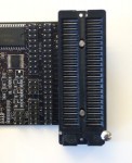
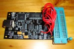
 The Dragon does not arrive ready for use. They give you a flexible prototyping area and a place where you can solder headers. There are lots of approaches that work. My choice, with which I’ve had good results, is to add pin headers to the HV Prog connector area and the adjacent 40-pin “EXPAND” connector, then add a 40pin ZIF socket in the prototyping area. This lets me use the Dragon for any supported combination of target and programming mode, merely by adding jumpers in the right place.
The image to the right (from the Atmel website) shows the end result:
The disadvantage of this approach is that changing jumper configuration is somewhat time-consuming and potentially error-prone. There are some clever alternative possibilities, though.
Jumpers: Lazy Method

Most of the approaches I’ve seen to jumper wiring on the Dragon involve ribbon cables with compression-fit connectors on one end and a bunch of individual single-pin sockets on the other. That works, but involves fabricating several such cables. At my local electronics store, I noticed the SchmartBOARD jumpers. These are nice stranded 3″ wires with a pin socket on each end, fitted with shrink-fit tubing for insulation and strain relief. Build quality seems good, and at about US$5 for a 10-pack (with a strip of 20 pin headers I’m sure you’ll find a use for) they’re reasonably cheap.
If you’re doing parallel programming, you’ll want to get two packs. The 3″ version has worked out fine for all the configurations I’ve used so far, though you may need a handful of longer jumpers if you’re programming 40-pin microcontrollers.
Programming Modes
There are several different ways for the Dragon to talk to your microcontroller. One of the easiest and most familiar is the six-wire ISP (in-system programming) bus. That’s a popular method as it requires relatively few pins, and lets you program the microcontroller without removing it from the circuit.
You can’t always use ISP, though. One reason is that some low-pin-count parts like the ATtiny11 don’t support it. Another is that ISP only works with certain combinations of fuse bit settings. Since you can set the fuse bits to arbitrary values using ISP (even values that make no sense), you can “brick” a microcontroller by applying fuse settings that don’t work and which you cannot change via ISP. Here are some specific examples:
- ISP depends on the reset pin acting as a reset rather than a general-purpose I/O. If you enable (set to zero) the RSTDISBL bit, ISP won’t work.
- Turning off (setting to one) the serial programming enable (SPIEN) bit will stop ISP working.
- Setting the clock bits to something that prevents the microcontroller from clocking reliably (e.g., telling it to use an external crystal when there isn’t one) will make ISP not work.
In some cases there are workarounds. For example, if you’ve turned on RSTDISBL, you can still get the chip to reset by applying +12V to the reset pin. If you’ve done something silly with the clock, you can sometimes get around it by applying an appropriate square wave (possibly generated by another AVR microcontroller) to the clock input and/or messing with the timing settings on your programmer.

However, the only completely general-purpose remedy is using either HVSP (high-voltage serial programming) or PP (parallel programming), depending on the specific microcontroller you’re trying to fix.
For the popular ATmega168 and ATmega328P parts, parallel programming is what you want. Start by looking at the AVR Dragon online help, specifically the list of supported devices. Find your device and the required programming mode (one of HVSP or PP). Look at the connection sheet (linked from the list of supported devices) and set the jumpers accordingly.
The image to the right (from the Atmel help website) shows the correct jumper settings for doing parallel programming on the ATmegaXX8(P) parts (where XX is 4, 8, 16 or 32).
Fixing Fuses
Once you have the jumpers set up and target microcontroller in the ZIF socket, actually fixing the fuses is quite simple. Just use the command-line “avrdude” utility with the options “-c dragon_pp -P usb” and program as usual. (Other programming software may work also. The Dragon is supported by Atmel’s AVR Studio software, though I have not used it myself.)
For help finding the correct fuse values, the Engbedded fuse calculator is quite useful. It even gives you the correct avrdude command-line arguments to cut and paste. Note, however, that unused/non-existent bits (like bits 3..7 of the extended byte on the ATmega328P) read back as all-one on the Dragon, while other programmers read them back as all-zero.
This means (again using the ATmega328P extended bits as an example), if you want to set the BOD level to 4.3v (BODLEVEL=100) you’ll get a verification error if you try to use ‘-U efuse:w:0x03:m’. To avoid that, use ‘-U efuse:w:0xfb:m’ instead. (The fuse gets set right either way. The latter method just avoids a misleading error report.)
If you do run into the verification error, answer “no” when avrdude offers to restore the old setting; if you say “yes” it’ll hang until interrupted.
Can AT90SCR100H reset FUSE – Settings by AVR Dragon ?
Seikou Isimaru @#1: That is a good question. I don’t see the AT90SCR100H listed in the table of supported devices in the Dragon documentation.
According to the data sheet, the AT90SCR100H supports serial and JTAG programming. Depending on what state the fuses are currently in, you might be able to use one of those methods.
I don’t think you can use parallel or high-voltage serial programming on the AT90SCR100H. If you try, please be careful as the rest of circuit to which your controller is connected may not be designed with 12V+ in mind.
I’m just speculating; I’d welcome comments from anyone who has actually tried it.
Great information!
Can you tell me how to “un-brick” a chip with bad fuse settings?
Tim @#3: That’s kind of the topic of the whole article above. To summarize:
If the problem is just that it won’t clock in-cicuit because you set the CKSEL bits to something silly, you can sometimes recover by feeding a slow (1KHz or so) square wave (at TTL levels: low=0V, high=5V) into the clock pin.
If you’ve disabled reset, you can force matters by applying +12V to the reset pin, then using your normal programmer.
If it’s something else wrong with the fuses, you need something like the AVR Dragon that can do HVSP or HVPP (depending on the chip).
Of course, if you’ve let out the magic smoke (or otherwise done actual damage to the chip), then there’s no saving it.
Thank you so for publishing this article.
I changed to parallel programming. It worked like a treat.
Thank you for your pointer.
Mat Hallam-Eames
hi
I tried to enter the section programming mode(parallel mode) ,but when
connect +12 to reset pin ,
current 250 mA and IC hot…
So where is my job wrong?
Antipa, you only need +12V on RST if you’ve disabled reset in the fuse settings. Even then, you just want a short pulse (100ms or so is plenty) to reset the chip and force it into programming mode.
The easiest way to do it is using the AVR Dragon or similar programmer that support HVSP. That will take care of all the timing details for you.
If the chip gets hot, that’s a bad sign; either something is already damaged, or is about to be.