The Raspberry Pi is an inexpensive ARM7-based single-board computer that runs Linux. Using it, together with an almost-equally-inexpensive GPS receiver module from Adafruit Industries, I was able to set up a reasonably good NTP server for my home network. While the hardware side was almost ridiculously easy, the software required a bit of effort, including building a custom kernel and building ntpd from sources. Full details after the jump.
Caveats
There are a few things I should mention up front, in the hopes of not wasting anyone’s time:
- I am not the first person to use a Raspberry Pi as a GPS-based time source with PPS. What I’m doing here is just taking hard work that a bunch of other smart people did and collecting in one place for convenience. Please see the “Credits” section.
- If you just need a local time source with minimal work, this is far from a “plug it in and it goes” solution. You’d almost certainly be better-served by an appliance product such as the Veracity VTN-TN.
- If you have a reliable, always-on high-speed Internet connection, consider just using machines in the NTP server pool as your time source.
- If all you care about is keeping the system time correct on a “human scale” (i.e., within a second or so), then there are much easier ways to do it, like a USB GPS dongle. (For starters, you won’t have to compile any software from source or hack any hardware.)
- This project requires building a custom kernel. If you aren’t comfortable doing that (or don’t know what that means) then you’ll probably be happier and learn more if you start with something easier.
- You’ll also have to do some soldering. It isn’t hard, but this isn’t really a good first soldering project either.
- Never hack hardware you can’t afford to destroy. Any time you connect something to the GPIO header on your Raspberry Pi, there’s the potential to wreck it if you screw up.
Parts List
- Raspberry Pi Model B Revision 1.0 (/proc/cpuinfo Revision field = 0002)
- Adafruit Pi Box (laser-cut acrylic enclosure)
- 16GB Class 10 SDHC card
- 5VDC 1A USB power supply
- generic USB-to-USB micro cable
- generic Ethernet cable
- CR1220 coin battery
- Adafruit Ultimate GPS Breakout board version 3
- Schmartboard 2″ F-F jumpers (5 needed)
With the exception of the last three items, that’s just the basics you’ll probably want to run the Raspberry Pi for any purpose.
Sourcing and Substitutions
The Raspberry Pi itself is getting easier to obtain, and newer Model B units come with 512KB 512MB of RAM (instead of the 256KB 256MB on my rev 1.0). Newer board revisions also have various other improvements. Get the newest one you can, but double-check the pin assignments on the GPIO header. I got my through Newark, but at the time of this writing they’re out of stock. Check around, and don’t pay much more than the $35.00 MSRP.
Model A boards are said to be starting to appear. They should work fine for this, but if you take this option you’ll need to provide your own USB Ethernet adapter (and possibly a self-powered USB hub).
Obviously you can use whatever enclosure you like, or none at all. (My workbench is cluttered with enough conductive objects that running caseless would end badly for me.) You’ll need access to the GPIO headers, so make sure you get a case that provides for that, or which you can easily modify.
There’s a lot of flexibility in choosing an SD card. 4GB would be plenty of space. You might be able to get away with 2GB if you made a concentrated effort to keep things small, but at the price differential between 2GB and 4GB is under a dollar, so why bother? Very early Pi releases had a bootloader which would choke on Class 10 cards; this has long since been fixed. There’s a detailed discussion of SD card choice including a compatibility list with specific models on the Pi Wiki. The usual advice about getting a name-brand card from a reputable vendor applies.
Any power supply that provides stable, clean 5VDC at 700ma or more should work. The Pi Wiki has a compatibility list. Don’t go cheap on this component unless you’re prepared to put a scope on the output and verify that the output is clean and in-spec while under load. Unstable power will cause intermittent problems.
If you have to go further than your junk box to source a USB or Ethernet cable, this may not be the best project for you.
The Adafruit Ultimate GPS Breakout board (based on the GlobalTop MTK3339 chipset) is a good value, works great and requires no fancy interfacing thanks to 3.3V outputs. It does require a small amount of soldering, but it’s all easy through-hole stuff. Try to get the revision 3 board, as it brings the PPS output to the breakout header. (You can add a PPS output to earlier revisions, but it requires soldering a jumper wire to a relatively tiny surface-mount pinout.)
You can get cheaper GPS modules, but remember that 1) you will not get better than about ±100ms accuracy without a PPS output, and 2) the Pi GPIO interface (including the serial UART) requires 3.3V inputs, meaning you’ll need level-shift circuitry if your GPS has 5V outputs.
SERIOUS WARNING: The Pi GPIO pins have no over-voltage protection. If you put more than 3.3V across them, you will wreck your Pi.
USB GPSen can be made to work, but once again you’ll need a PPS output to get any real accuracy. This will almost certainly require hardware hacking (very likely literal, as in “with a hacksaw”).
The CR1220 coin battery is backup power for the GPS module, so it can “warm start” when the system powers up. It is optional, but if you have it, you’ll get a fix (and PPS pulses) within a few seconds of power-up rather than a few minutes.
There are plenty of ways to connect the GPS module to the Pi. I chose the Schmartboard jumpers because they’re easy to use and non-permanent. (Note that these jumpers are sold in a package of ten. You need five individual jumpers — half a package. Not five packages.)
Hardware Assembly
Put your Pi in its enclosure. Make sure you will be able to connect jumpers to GPIO pins P1-04, P1-06, P1-08, P1-10 and P1-12. If you hold the Pi with the component side toward you and the yellow composite video output toward the top, the GPIO pins are in the top left corner. There are two rows of 13 pins each on the GPIO header. The ones you need are all on the row closest to the long edge of the Pi. Within that row, they’re on the end close to the corner. See the pinout diagram.)
With the Adafruit Pi Box, I had to cut a small notch using a scroll saw.
Assemble the GPS breakout: Solder on the battery holder and headers. (Note that short end of the header pins gets inserted through the back of the board! I wasn’t paying attention and put it on the component side on the first try, then had to de-solder it…) Insert the CR1220 battery.
Do not connect the GPS to the Pi yet. It probably wouldn’t hurt anything, but since the serial UART on the Pi is configured as the system console by default, it would be prudent to do some of the software changes first. (Also, if your Pi works fine during setup then stops once you hook up the GPS, you’ll have a better idea of where you went wrong.)
OS Installation and Setup
I started with a stock Raspbian “Wheezy” image from the Pi Foundation. Any reasonable distribution should work, but you’ll need to make appropriate substitutions (in package manager commands, file locations and kernel sources) if you take a different option.
The Pi Wiki has detailed instructions for downloading an OS image and setting up your SD card.
Go through basic configuration and get connected to the Internet. Instructions for setup and first-time config are can be found on h2g2.
Once you have completed the initial configuration, everything else can be done from the command line via SSH. If you wish, you can disconnect the console from your Pi and work from another machine on your network.
Update your system and packages to the latest version:
sudo apt-get update
sudo apt-get upgrade
sudo apt-get dist-upgrade
sudo apt-get autoclean
Turning Off the Serial Console
Important: In this section, I talk about a serial port on the Pi, and indeed that’s exactly what I mean. However, it is absolutely not the familiar EIA RS-232-C kind of serial port. A garden-variety serial port uses ±15V signalling, which will kill your Pi. Even TTL-level adapters that use 5V are out. The Pi wants 3.3V serial levels ONLY.
In Raspbian, the default is to use the Pi’s serial UART as a console. This is handy, because you can use it to watch the printk output from the kernel, before the system comes up into user-space. But for this project, we need to use the serial port for another purpose: reading NMEA sentences from (and sending commands to) the GPS.
Fortunately, this is really easy: Edit /boot/cmdline.txt to remove the text console=ttyAMA0,115200 . (Aside: Whenever I say “edit a file”, please take it as read that I mean “make a backup copy of that file, then edit the original”.)
Here is what my cmdline.txt looks like after the edit:
dwc_otg.lpm_enable=0 console=tty1 root=/dev/mmcblk0p2 rootfstype=ext4 elevator=deadline rootwait
Once you have made this change, shut down the Pi and remove power.
Connecting the GPS
With the power to the Pi disconnected, use jumpers to connect the following (all listed with Pi side first, then “to”, then the GPS side).
- P1-01 (+3.3V power) to >VIN (supply voltage)
- P1-06 (Ground) to GND
- P1-08 (UART0_TXD) to >RX (serial data in)
- P1-10 (UART0_RXD) to <TX (serial data out)
- P1-12 (GPIO18) to PPS (pulse-per-second output)
Double-check your wiring.
Boot up the Pi and confirm things seem to be working normally.
Verify you are receiving 9600 baud NMEA sentences on serial port /dev/ttyAMA0. You can do this with a terminal program like minicom, or by something like:
sudo stty -F /dev/ttyAMA0 9600
cat /dev/ttyAMA0
(Press ^C to exit.) You should see output not unlike the following:
$PGTOP,11,2*6E
$GPGGA,222249.000,4116.6600,N,12905.2500,E,2,11,0.75,29.9,M,-23.6,M,0000,0000*6F
$GPGSA,A,3,31,30,11,20,01,23,22,32,16,25,14,,1.51,0.75,1.32*02
$GPGSV,3,1,12,31,71,003,34,32,54,318,30,30,44,164,24,48,36,237,30*7B
$GPGSV,3,2,12,14,31,070,31,20,27,316,23,01,27,270,32,22,26,143,17*7F
$GPGSV,3,3,12,16,18,180,23,25,18,045,33,11,14,248,20,23,06,289,18*77
$GPRMC,222249.000,A,4116.6600,N,12905.2500,E,0.01,304.60,140213,,,D*74
$GPVTG,304.60,T,,M,0.01,N,0.02,K,D*3A
(The specific numbers you see will be different. I have redacted my location data in the above for privacy.) If you stuff like the above, it means your GPS module is working, and proves that everything is hooked up right (with the possible exception of the PPS output).
You may see a lot of empty fields:
$PGTOP,11,2*6E
$GPGGA,235948.799,,,,,0,0,,,M,,M,,*4E
$GPGSA,A,1,,,,,,,,,,,,,,,*1E
$GPGSV,1,1,01,14,,,32*7C
$GPRMC,235948.799,V,,,,,0.00,0.00,050180,,,N*47
$GPVTG,0.00,T,,M,0.00,N,0.00,K,N*32
If so, that means your GPS doesn’t have a fix yet. That’s normal when you first power it on. Give it about five minutes and see if it changes. (If you installed the CR1220 battery, subsequent power-ups will give you a fix much faster.)
If you still get output with lots of empty fields (like the second example) after the GPS has been powered up for a few minutes, you may be in a location where you’re not getting a good signal. (If you’re indoors and in a multi-story building and/or have a metal roof, that’s likely the case.) Relocate the GPS or try an external antenna.
The $PGTOP sentence is a proprietary GlobalTop extension. You won’t see it if you’re using another brand of GPS module, but that’s OK — you don’t need it.
Compiling a Custom Kernel
The problem with the stock kernel (for the purposes of this project) is that it doesn’t provide any way for user-space programs to use the PPS signal from the GPS module in a sufficiently low-latency way. Sure, we could poll the GPIO pin and see the PPS signal, but what we really want is for it to cause an interrupt, then have a low-level interrupt handler make a note of exactly when that happened, and finally pass that information into user-space in a useful way.
Fortunately, there’s already a standard PPS API (for getting PPS information into user-space), a Linux implementation of ditto, and a kernel driver for GPIO-based PPS sources in the mainline 3.6.x kernel sources. All we really need to do is to enable that driver, and add a tiny bit of initialization code to tell it which GPIO pin is the PPS interrupt source. But, that still means building our own kernel from sources.
(Update: If you really don’t want to do this part, I’ve created an archive containing my kernel and related files. It is a 47MB bzipped tarball. Download it, unpack it in an empty temporary directory on your Pi, then skip to the “Transferring Updates to the Pi” section. Instead of the source locations I talked about in that section, get the files from where you unpacked the tarball. It’s really better to build your own, though, as I don’t plan on doing regular updates to this one…)
The Kernel Compilation page on the Pi Wiki is a great resource for this section. Please look there if you have trouble or need a more general process. I’ve tried to distill it down to the specific steps that worked for me.
This step will go a whole lot faster if you have another Linux box (like a desktop PC or laptop) that’s much faster than the Pi. It’s OK if it’s a totally different architecture — we can cross-compile.
The directions below are assuming your build machine is running Ubuntu 12.04.1LTS 64-bit Server, and is connected to the Internet. (Things should be the same or nearly so on any recent-vintage Ubuntu. If you’re using another distro, you may need to do some translation.)
Get the Cross-Development Tools
We need a set of development tools that will allow us to build programs on our big speedy system that can run on the Pi. (We’re going through this hassle because building a kernel takes hours and hours on the Pi. It does work, though.)
The good news is that there are pre-built packages for everything we need in the default repositories, and the package manager make it all easy to install:
sudo apt-get install gcc-arm-linux-gnueabi make ncurses-dev
Get the Kernel Sources
At the time of this writing, platform support for the Pi wasn’t yet in the mainline kernel sources. There are lots of ways to get to a working kernel, but you’ll probably experience the least friction if you stick with something close to what stock Raspbian is using. For now, at least, that means using the rpi-3.6.y branch from GitHub:
wget 'https://github.com/raspberrypi/linux/archive/rpi-3.6.y.tar.gz'
tar xvzf rpi-3.6.y.tar.gz
mv linux-rpi-3.6.y linux
Your kernel sources should already be in a pristine state, but make sure. cd to the top level of the kernel sources (if you aren’t there already) and run the command
make mrproper
(Note that “make mrproper” removes any kernel configuration that’s present. If you “make mrproper” again later, remember you’ll have to do all the configuration stuff again.)
Get the Running Configuration
Rather than configure the kernel from scratch, we’ll use the kernel already running on the Pi as a starting place. The configuration file used to build the running kernel is compiled in to the kernel itself, and is accessible via the /proc filesystem. To use it:
- Log in to the Pi.
gunzip -c /proc/config.gz >config- Copy
configto .config (note the leading dot!) in the top level of the kernel sources on the machine where you’re doing the build.
Figure out the Location of Your Cross-Development Toolchain
The tools used on your build host to build programs to run on the Pi all have a common prefix, in this case arm-linux-gnuabi-. For subsequent steps, we’ll need to know this prefix and also the full path to the cross-development tools. To save time and typing, it’s handy to put this information in an environment variable.
To find out where your cross-tools are:
which arm-linux-gnueabi-gcc
This should give you an answer like “/usr/bin/arm-linux-gnueabi-gcc”. Assign this value to the environment variable CCPREFIX, omitting the trailing gcc (but leaving the trailing dash), like this:
export CCPREFIX='/usr/bin/arm-linux-gnueabi-'
If you’re going to be doing a lot of cross-development, it might be handy to put the above command in your profile, or in a file you can source.
Apply the Configuration
Configure your kernel sources using the config file you pulled from the running kernel on the Pi:
make ARCH=arm CROSS_COMPILE=${CCPREFIX} oldconfig
Note: Normally, the above command will complete without interaction. However, if the kernel you’re building is not exactly the same version as the one running on your Pi, you may be asked additional configuration questions at this point. If you don’t know how to answer, the best advice I can offer is 1) go on the Pi and do a “sudo apt-get update” and a “sudo apt-get dist-upgrade” to see if there is a newer kernel that’s closer to the one you’re building, or 2) use the default suggestions.
Make Necessary Configuration Changes
One of the reasons we’re building a new kernel is that we need a feature that isn’t available in the stock Raspbian kernels. To enable this feature, we’ll need to modify the configuration. There are several ways to do this, but the easiest is probably the interactive menu-based config editor:
make ARCH=arm CROSS_COMPILE=${CCPREFIX} menuconfig
To make the necessary changes:
 When the menu appears, use the arrow keys to scroll down to Device Drivers then hit Enter.
- Scroll down to PPS Support then hit Enter again.
- Press ‘M’ to enable PPS support as a module.
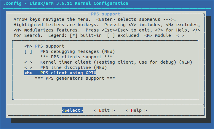
- Scroll down to PPS client using GPIO.
- Press ‘M’ to enable the GPIO PPS client as a module.
- Verify that your screen looks like the screenshot to the right (click to enlarge):
- Hit the right arrow then Enter to exit up to the previous menu. Do so twice more.
- When asked if you wish to save, hit Enter to select Yes.
Note that you can also build the PPS support into the kernel directly (by hitting ‘Y’ instead of ‘M’ in steps 3 and 5, above). Doing so will make your kernel a little larger (and slightly slower to boot) but you won’t have to worry about loading a module before you can use the PPS signal. The general policy in Raspbian seems to be to make everything possible a module, so I’m following their lead
Register a Platform Device as a PPS Source
In order for the PPS support in the kernel to do us any good, we need to define the source of the PPS signal. To accomplish this, we must edit the board-specific platform file for the Pi (arch/arm/mach-bcm-2708/bcm2708.c) and make three changes:
- Include the header linux/pps-gpio.h (to get typedefs for some data structures we’ll need).
- Define a static data structure that specifies the GPIO pin we want to use and how exactly to use it.
- Call the bcm_register_device() function, passing in a pointer to the data structure from (2), to add the PPS source.
Here is a context diff of the changes:
--- bcm2708.c.0	2013-02-15 11:08:40.497566132 -0600
+++ bcm2708.c	2013-02-15 12:34:58.782693974 -0600
@@ -55,6 +55,7 @@
 #include <mach/system.h>

 #include <linux/delay.h>
+#include <linux/pps-gpio.h>

 #include "bcm2708.h"
 #include "armctrl.h"
@@ -64,6 +65,19 @@
 #include <linux/broadcom/vc_cma.h>
 #endif

+/* PPS-GPIO platform data */
+static struct pps_gpio_platform_data pps_gpio_info = {
+	.assert_falling_edge = false,
+	.capture_clear= false,
+	.gpio_pin=18,
+	.gpio_label="PPS",
+};
+
+static struct platform_device pps_gpio_device = {
+	.name = "pps-gpio",
+	.id = -1,
+	.dev = { .platform_data = &pps_gpio_info },
+};

 /* Effectively we have an IOMMU (ARMVideoCore map) that is set up to
  * give us IO access only to 64Mbytes of physical memory (26 bits).  We could
@@ -708,6 +722,7 @@
 	bcm_register_device(&bcm2708_vcio_device);
 #ifdef CONFIG_BCM2708_GPIO
 	bcm_register_device(&bcm2708_gpio_device);
+	bcm_register_device(&pps_gpio_device);
 #endif
 #if defined(CONFIG_W1_MASTER_GPIO) || defined(CONFIG_W1_MASTER_GPIO_MODULE)
 	platform_device_register(&w1_device);
You can download a copy of the above patch if that’s easier than cutting-and-pasting. Or, you can download my original and patched versions of the bcm2708.c file. (If you are using my pre-patched file, please make sure the original version I started from matches your original. Future kernels may have other updates to this file that you don’t want to lose.)
Note that I chose to use GPIO pin 18 merely because it was adjacent to the other pins I was using to connect my GPS module. You can certainly choose a different pin if you have a reason to do so.
Compile the Kernel
Go back to the top level of the kernel source tree, and build the kernel:
make ARCH=arm CROSS_COMPILE=${CCPREFIX} -j5
(The above example is for a four-core system. Replace the “5” with the number of cores you have plus one. If you prefer a single-threaded build, just omit the “-j5” entirely.)
The build process will take a few minutes or a few tens of minutes depending on your system.
Install the Modules
You’ll also need the modules that go with the kernel you just built. Since we’re not building on the system where this kernel is going to run, we’ll need to install the modules to an alternate location:
make ARCH=arm CROSS_COMPILE=${CCPREFIX} INSTALL_MOD_PATH=~mylogin/temp_modules modules_install
Where ~mylogin/temp_modules is the directory where you want the modules installed. This should be an absolute path to a directory that does not already exist, and you should have write permission in the parent directory.
Obtaining the GPU Firmware and Libraries
You’ll also want to get the GPU firmware, libraries and utilities (such as vcgencmd) that match the new kernel you’ve built. To obtain them:
wget 'https://github.com/raspberrypi/firmware/archive/next.tar.gz'
tar xvzf next.tar.gz
Transferring Updates to the Pi
At this point, you’ll need to transfer a number of files and directories from your build host to the Pi. For all of the following cases, if there is an existing item of the same name already on the Pi, you’ll need to delete it or (much better) move it aside.
- The kernel itself: from linux/arch/arm/boot/zImage to /boot/kernel.img
- The modules directory: from ~mylogin/temp_modules/lib/modules/3.6.11 to /lib/modules/3.6.11
- The kernel firmware directory: from ~mylogin/temp_modules/lib/firmware to /lib/firmware . Note that if you have any custom firmware (such as for a wireless network adapter), you’ll need to copy it back into the new /lib/firmware directory.
- Bootloader-related files:
- firmware-next/boot/bootcode.bin to /boot/bootcode.bin
- firmware-next/boot/fixup.dat to /boot/fixup.dat
- firmware-next/boot/start.elf to /boot/start.elf
- GPU-related files: from firmware-next/hardfp/opt/vc to /opt/vc
Note that the above assumes your kernel version is 3.6.11. If not, your modules subdirectory will have a different name, and you must adjust the instructions accordingly.
Once all of the above have been transferred, run sync a couple times then reboot your Pi.
Verifying Kernel, GPU Utils and PPS Input
We just made some major changes, so it’s a good time to make sure everything is working. Here’s a minimum list of things I’d suggest you check — feel free to add more :
- Does the Pi boot up and can you log in?
- Does uname -a show the kernel version you expect?
- Do you see anything in the output of dmesg that looks like an error or warning? (Note that lots of people get warnings about “missed completion of command 18” from the SD card DMA code. That is probably harmless and in any case is unlikely to have anything to do with the changes you just made.)
- Try vcgencmd measure_temp. It should give you temperature output similar to temp=50.2’C. If you get an error from this command, suspect a problem with the stuff in /opt/vc/.
If all seems well, try loading the pps_gpio module:
sudo modprobe pps_gpio
Once you have done so, the output of lsmod should include a couple of lines like:
Module                  Size  Used by
pps_gpio                2124  0
pps_core                7254  1 pps_gpio
(Don’t worry if the sizes you see are different from the above. Also, if you built PPS and PPS GPIO support directly into the kernel rather than as modules, you don’t need to do the modprobe, nor will you see pps_gpio or pps_core in the modules list.)
Run dmesg. The output should include lines like:
[   89.551595] pps_core: LinuxPPS API ver. 1 registered
[   89.551622] pps_core: Software ver. 5.3.6 - Copyright 2005-2007 Rodolfo Giometti <giometti@linux.it>
[   89.559630] pps pps0: new PPS source pps-gpio.-1
[   89.559696] pps pps0: Registered IRQ 188 as PPS source
(The timestamps will differ in your output. You should see these lines regardless of whether you built PPS support as a module or as an intrinsic part of the kernel. If you chose a different GPIO pin, the IRQ number you see will not match the example.)
Finally, you should see a new device special file /dev/pps0:
crwxrwxrwt 1 root tty 248, 0 Feb 15 14:30 /dev/pps0
If the PPS support is present and connected to an interrupt, the next thing to check is if PPS pulses are being received from the GPS module. To verify:
sudo apt-get install pps-tools
sudo ppstest /dev/pps0
This should produce output similar to:
trying PPS source "/dev/pps0"
found PPS source "/dev/pps0"
ok, found 1 source(s), now start fetching data...
source 0 - assert 1360961986.896233919, sequence: 1777 - clear  0.000000000, sequence: 0
source 0 - assert 1360961987.896296264, sequence: 1778 - clear  0.000000000, sequence: 0
source 0 - assert 1360961988.896357502, sequence: 1779 - clear  0.000000000, sequence: 0
source 0 - assert 1360961989.896418637, sequence: 1780 - clear  0.000000000, sequence: 0
(Press ^C to exit.) Your sequence numbers and timestamps will be different from the example, but the timestamps should be very close to one second apart, from each line to the next.
Loading Modules and Creating Device Symlinks on Boot
We want to use the GPS NMEA stream and PPS input with ntpd, which we want to start automatically at boot time. There are a couple of minor obstacles to this: First, we need to make sure the necessary modules get loaded without manual intervention (unless you’re not using modules, in which case: never mind). Second, ntpd expects its input to come from device files with very specific names (which don’t match the defaults).
These are both easy problems to solve.
To ensure a module is loaded at boot time, just append its name (on a line by itself, without the “.o”) to the file /etc/modules. Example command:
sudo sh -c 'echo pps_gpio >>/etc/modules'
To create symlinks in /dev from the default device files to the names ntpd expects, create a new file /etc/udev/rules.d/09-pps.rules with contents as follows:
KERNEL=="ttyAMA0", SYMLINK+="gps0"
KERNEL=="pps0", OWNER="root", GROUP="tty", MODE="0777", SYMLINK+="gpspps0"
Once you have done both of the above, reboot the Pi. When it comes back up, check that the modules are loaded and that you have symlinks called /dev/gps0 and /dev/gpspps0.
Building ntpd with PPS Support
The stock ntpd (4.2.6p5) at the time of this writing does not appear to have support (or at least not working support) for PPS input. So, we’ll have to build our own from source.
First, remove the stock NTP package if it is installed:
sudo apt-get remove ntp
Next, install the development libraries and header for Linux capabilities support:
sudo apt-get install libcap-dev
This package will allow us to build an ntpd which can do things like access the PPS ticker and slew the system clock without having to run as root.
Then, download the NTP sources from the official web site. There are two choices: production (older but more stable) and development (newer but less well-tested and potentially flaky). I opted for the development version (4.2.7p354 at the time of this writing), but that is a questionable choice.
Unpack the source archive and cd into the directory containing the source. Configure as follows:
./configure --enable-linuxcaps --with-NMEA --with-ATOM
This enables support for the aforementioned libcap stuff, reading NMEA sentences from the GPS module, and reading PPS pulses via the PPS API.
Once configuration is complete, build and install:
make
sudo make install
This will install the NTP utilities (including ntpd) under /usr/local/.
Configuring and Running ntpd
The system-provided script for launching ntpd needs some minor edits to work with ntpd installed in /usr/local/bin instead of /usr/sbin. In the file /etc/init.d/ntp, add /usr/local/bin to the beginning of the PATH, and set DAEMON to /usr/local/bin/ntpd. For reference, I have provided a copy of my /etc/init.d/ntp file. (If you’re downloading the linked copy, remember to make it owned by root and to give it execute permission.)
You’ll also need to configure ntpd via the file /etc/ntpd.conf. Here is what I am using:
driftfile /var/lib/ntp/ntp.drift
statsdir /var/log/ntpstats/
statistics loopstats peerstats clockstats
filegen loopstats file loopstats type day enable
filegen peerstats file peerstats type day enable
filegen clockstats file clockstats type day enable

server 0.debian.pool.ntp.org iburst
server 1.debian.pool.ntp.org iburst
server 2.debian.pool.ntp.org iburst
server 3.debian.pool.ntp.org iburst

server 127.127.20.0 mode 16 prefer
fudge 127.127.20.0 flag1 1 time2 0.400

restrict -4 default kod notrap nomodify nopeer
restrict 127.0.0.1
(If you prefer, there is also a copy of the above available for direct download.) Most of that’s pretty standard stuff, but note that we allow queries from anywhere; add “noquery” to the first restrict line if that’s not what you want. Since the stock Raspbian kernel doesn’t do IPv6, I’ve omitted IPv6 configuration from the config file. Also, the following lines deserve further explanation:
server 127.127.20.0 mode 16 prefer
fudge 127.127.20.0 flag1 1 time2 0.400
Any server with a numeric IP address where the first two octets are 127.127 is given special treatment by ntpd. The third octet is interpreted as a code specifying a driver for a locally-connected time source. A list of the available drivers can be found on the Reference Clock Support page — the “Type” codes listed near the bottom of the page are the supported values for the third octet. Type “20” is the generic NMEA driver.
The fourth octet specifes a unit number. The driver looks for /dev/gpsN and /dev/gpsppsN where N is the unit number (in our case, 0).
The mode number specifies the GPS port speed and which NMEA sentences should be recognized. The value used above (16) means 9600 baud, all supported sentences. See the Generic NMEA GPS Receiver page for full documentation of the mode values (and the fudge values on the following line).
On the fudge line, “flag1 1” means to enable PPS signal processing. (The default is to disable it.)
The “time2” value on the fudge line is the average time from the “real” top of the second to the time the first recognized NMEA sentence for that second is fully received. The reasons for needing to know this are complicated, but they boil down to this: The NMEA stream tells ntpd what second it is, and the PPS pulse tells ntpd exactly when that second starts. If they’re too far apart, ntpd doesn’t trust that it knows which second the PPS pulse goes with. The time2 offset is there to give it a hint.
The real explanation, quoting from Juergen Perlinger on support.ntp.org:
And now the truth about the PPS locking: actually only the sub-second part of the difference between PPS time stamp and (receive time stamp – fudge time2) is evaluated and checked. If this difference is less than 400ms or bigger than 600ms (which is equivalent to -400ms) the receive time stamp will be substituted with the properly adjusted PPS time stamp. This might sound a bit complicated, but if you have a device that sends the data before the associated PPS pulse, you can use the proper negative value for fudge time2 and compensate for that behaviour.
Finally, to launch ntpd:
sudo /etc/init.d/ntp start
This should produce output that looks like:
[ ok ] Starting NTP server: ntpd.
Verifying Correct Operation
Make sure that the ntpd process is running. If not (or even if it is), check the end of /var/log/daemon.log for errors or warnings.
Check that ntpd has the /dev/gps0 and /dev/gpspps0 device files open:
sudo lsof /dev/gps0 /dev/gpspps0
This should produce output similar to:
COMMAND  PID USER   FD   TYPE DEVICE SIZE/OFF NODE NAME
ntpd    3899  ntp    5u   CHR 204,64      0t0    8 /dev/ttyAMA0
ntpd    3899  ntp    6u   CHR  248,0      0t0 3127 /dev/pps0
(You will likely see different PIDs and node numbers in your output.)
Finally, try the following command:
ntpq -p
You should see output something like the following:
     remote           refid      st t when poll reach   delay   offset  jitter
==============================================================================
oGPS_NMEA(0)     .GPS.            0 l   42   64  377    0.000   -0.010   0.004
-paladin.latt.ne 216.171.124.36   2 u   43   64  377   63.209   -1.125   3.375
*216.45.57.38    69.25.96.13      2 u   60   64  377   45.596    1.644   0.623
+echelon.no-such 209.81.9.7       2 u   46   64  377   56.903    1.915   1.314
+bindcat.fhsu.ed 132.163.4.103    2 u   62   64  377   44.217    1.354   0.546
The specific values and hostnames you see will differ. The important things are:
- Is there a row where the “remote” is GPS_NMEA(0)? If so, that means that the NMEA driver is in use.
- On that row, is the “reach” value something greater than 0? If it is not 377, does it increase if you wait a few minutes? (The “reach” value is the octal representation of an 8-bit vector of the most recent attempts to the source for that row. A “1” bit represents a success. The least-significant bit is the most recent attempt.)
- On that row, is the first character a ‘o’ (lower-case O as in Oscar)? That means that the PPS source is being used. Note that it may take a couple minutes to reach this state; it is normal to see a ‘*’ when you first start ntpd. An ‘x’ is bad.
- After ntpd has been running for a few hours, is the “jitter” value on that row a small number? (The number is in milliseconds. You should expect jitter to converge on a value that’s 10µs or less. In other words, 0.010 or less in the ntpq output.)
Other Notes
There are a some obvious opportunities for improvements here:
- By default, the GPS module sends a number of sentences which aren’t needed for time synchronization. Worse still, some of these (notably GPGSV) vary in length according to the number of satellites overhead (and the position and signal strength of same). The GPGGA sentence is recognized by the ntpd NMEA driver and seems to always precede GPGSV, so it doesn’t cause major problems, but it still seems like it would be a good idea to disable the un-needed sentences, and to use only the shortest ntpd-supported one (GPRMC?).
- Routing the NMEA data through gpsd would make it available for other applications on the system while (in theory, anyway) not compromising accuracy. I made some attempts at this, but the stock gpsd (3.6) doesn’t seem to handle the PPS stuff properly (or, I’m not using it properly).
- It would be nice to get email or SNMP trap notification of various problems. Examples include poor GPS signal strength, long time to first fix after power-up and excessive jitter.
- Adding an additional time source such as a Chronodot, DS1307 or WWV receiver would be a nifty hack.
- Mounting the GPS module inside the Pi case and using non-temporary wiring would make things more tidy.
- The Ethernet interface on the Pi is actually a USB device, driver via polling. That means there’s significant built-in jitter. I’ve found this amounts to about
50µs500µs on my local network. Not bad, but not great either. It might be possible to get better timing properties by adding an ENC28J60-based interface to the SPI bus on the Pi. That’s approaching the point where “start with a different platform” is a whole lot less work, though.
I’ve also identified some things that seem useful but actually aren’t:
- Increasing the port speed is tempting, but probably counter-productive. (A missed or garbled sentence is much worse that one that arrives a few milliseconds sooner or later.)
- The GPS module is capable of updating at up to 10Hz, but increasing the update rate won’t help. Only the first update during a given second will be considered by ntpd.
An interesting thought experiment: How do you tell time (at all, to say nothing of accurately) if there’s no GPS signal, no WWV and no Internet? One thing that comes to mind is that you can use an accelerometer to measure “down”, a flux-gate compass to find “North” and then use an aimable optical (or RF) sensor to measure the position of the sun relative to down and North…
Credits
Thanks to the following for their hard work, which I just put together in a more-or-less obvious way:
- davidk on Open Collector for his Raspberry Flavored Time article
- all the folks on the NTP PPS thread over on the Raspberry Pi fora
- everyone who contributed to the RPi Kernel Compilation article on the eLinux.org Wiki
- whomever maintains the NTP docco pages at udel.edu
- the Raspberry Pi Foundation
- the NTP Contributors
- Limor “Ladyada” Fried
- Dennis, Ken and Linus, and more generally everyone who contributed to the Linux kernel, the GNU tools and/or Debian
Edited 20130218 DGH: Corrected figure for jitter on local Ethernet.
Edited 20130218 DGH: Added missing Credits section.
Edited 20130511 DGH: Corrected Pi RAM sizes per HR.
Edited 20130520 DGH: Added note about custom firmware per HR.
Edited 20130526 DGH: Fixed broken download links.
Edited 20130526 DGH: Added downloadable kernel archive.
In regards to filtering out the relevant NMEA messages, check out the Unit Calibration bit of this :
http://open.konspyre.org/blog/2012/10/18/raspberry-pi-time-server/
Paul @#1: Thanks, that’s good information.
However, I think I’ve convinced myself of a couple things that make it not as important as I first suspected:
1) The GlobalTop MTK3329 PA6H chip in my rev. 3 module always outputs a GPGGA sentence as the second thing at the top of every second (right after the fixed-length PGTOP). This is one of the sentences that the ntpd NMEA driver understands, and the first recognized sentence is the one that matters.
2) Even if the order of sentences were random, we’ve got PPS. It doesn’t matter precisely when ntpd figures out which second we’re in, because it always knows exactly when that second starts. It would only start to be a problem if we got the fudge “time2” value horribly wrong.
We’ll get a correct lock if NTPD sees a recognized sentence within +/-400ms of the time2-adjusted PPS pulse. At 9600bps, that means that to throw us off, it would take (9600 bits/s / 8 bits/byte) * 0.800s = 960 bytes difference between the best and worst cases for the arrival of the first driver-recognized sentence.
For comparison, a typical one-second block of output with the default settings is a little under 500 bytes.
Note to self (and readers): Explore using PTP instead of or in addition to NTP. (Thanks to lupus_yonderboy for the idea.)
Wow, this piece of writing is nice, my sister is analyzing such things, thus I
am going to tell her.
Just a small point of clarification…
“The Raspberry Pi itself is getting easier to obtain, and newer Model B units come with 512KB of RAM (instead of the 256KB on my rev 1.0).”
Should read 512MB and 256MB respectively (based on the model B info at http://www.raspberrypi.org/faqs)
HR @ #5: You are quite correct. Thanks. I have fixed the article text.
One further thing, if you have any custom firmware, you’ll need to move it back into the /lib/firmware directory.
My wireless dongle stopped working and it was only after checking dmesg that I realised I didn’t have the firmware in the folder. A copy from the old firmware folder to the new one fixed it up.
HR @ #7: That’s a good point. I have updated the article to add a note about custom firmware to the instructions for transferring the new kernel files. Thank you for the feedback.
Thx for the good Article.
I have one Question show the putput from ntptime you that there is the PPSSignal is set?
Your links to your patch (http://mythopoeic.org/pi-ntp/source-download/bcm2708-pps.patch) and the original and patched version don’t seem to exist any more.
Any chance of also putting up the compiled kernel and modules?
Andy @#10: You’d think I would have figured out how to write a working link by now, but apparently not. I’ve fixed the download links. Thanks for letting me know.
I don’t see any reason why I couldn’t put the kernel and modules up if that would be helpful. (It may be a few days, though…)
Nils @#9:
> I have one Question show the putput from ntptime you
> that there is the PPSSignal is set?
I’m not sure I understand your question, but I’ll try to answer what I think you’re asking: How you can tell PPS is working from the output of ntptime?
You can’t tell directly. However, if you run the ntptime command on the time server itself (not on a client) after it has been running for a while, you should see a very low figure for estimated error. (Mine is 2µs.) Without PPS, it would be in the tens or hundreds.
It is probably better to run “ntpq -p” on the time server, and make sure you see a line that starts with “oGPS_NMEA”.
Andy @#10: Compiled kernel and modules are now available for download. See the link in the third paragraph under “Compiling a Custom Kernel”.
My estimated error is round about 1usec.
The output from ntpq -p is “oGPS_NMEA” but in the Documentation from the ntp http://www.ntp.org/ntpfaq/NTP-s-config-adv.htm#Q-CONFIG-ADV-PPS-VERIFY they say the PPSSignal should set. But my Output have it not. So i am confused if the NTP Server is running correctly.
Here is my output:
ntpq -p; ntptime;
remote refid st t when poll reach delay offset jitter
==============================================================================
oGPS_NMEA(0) .GPS. 0 l 26 64 377 0.000 0.014 0.001
ntp_gettime() returns code 0 (OK)
time d5505ca9.2bff68f0 Wed, May 29 2013 10:53:29.171, (.171866728),
maximum error 13942 us, estimated error 0 us, TAI offset 0
ntp_adjtime() returns code 0 (OK)
modes 0x0 (),
offset 12.464 us, frequency -50.330 ppm, interval 1 s,
maximum error 13942 us, estimated error 0 us,
status 0x2007 (PLL,PPSFREQ,PPSTIME,NANO),
time constant 6, precision 0.001 us, tolerance 500 ppm,
Nils @#14: I’m a little confused, but I think what’s going on here is that there are two different things that can use the PPS signal: the NTP server itself, and the Linux kernel’s own idea of time.
I *think* the PPSFREQ and PPSTIME flags in the ntptime output are telling you about the kernel. (Anyone who knows better, please correct me!)
In the setup I talk about above, ntpd is using /dev/pps0 directly.
One way to know for sure would be to unplug the PPS input wire, and see how the output changes…
I have unplug the whole GPS Module and thats the Output:
ntpq -p; ntptime
remote refid st t when poll reach delay offset jitter
==============================================================================
GPS_NMEA(0) .GPS. 0 l 241 8 0 0.000 0.000 0.000
ntp_gettime() returns code 0 (OK)
time d553151a.435fb2d4 Fri, May 31 2013 14:24:58.263, (.263179025),
maximum error 21820 us, estimated error 4 us, TAI offset 0
ntp_adjtime() returns code 0 (OK)
modes 0x0 (),
offset 0.701 us, frequency -50.447 ppm, interval 1 s,
maximum error 21820 us, estimated error 4 us,
status 0x2007 (PLL,PPSFREQ,PPSTIME,NANO),
time constant 3, precision 0.001 us, tolerance 500 ppm,
PPSFREQ and PPSTIME still there the only things that have change is the “o” befor the peer.
Ok, thanks for the confirmation.
Based on that, my suggestions are:
1) Use “sudo ppstest /dev/pps0” to verify that your kernel has PPS support, that the driver is loaded, and that your pulse source is working and connected properly.
2) If (1) works, check the output of “ntpq -p” for a line that starts with “oGPS_NMEA(0) .GPS.” to see if ntpd is using the time source. (If the line does not start with a lower-case ‘o’, it isn’t.)
sudo ppstest works:
sudo ppstest /dev/pps0
trying PPS source “/dev/pps0”
found PPS source “/dev/pps0”
ok, found 1 source(s), now start fetching data…
source 0 – assert 1370003512.085565327, sequence: 82 – clear 0.000000000, seque nce: 0
source 0 – assert 1370003513.085565129, sequence: 83 – clear 0.000000000, seque nce: 0
source 0 – assert 1370003514.085567930, sequence: 84 – clear 0.000000000, seque nce: 0
source 0 – assert 1370003515.085564729, sequence: 85 – clear 0.000000000, seque nce: 0
source 0 – assert 1370003516.085565531, sequence: 86 – clear 0.000000000, sequence: 0
source 0 – assert 1370003517.085564332, sequence: 87 – clear 0.000000000, sequence: 0
source 0 – assert 1370003518.085564136, sequence: 88 – clear 0.000000000, sequence: 0
and the ntpq- p also:
ntpq -p; ntptime
remote refid st t when poll reach delay offset jitter
==============================================================================
oGPS_NMEA(0) .GPS. 0 l 7 8 77 0.000 0.019 0.001
Everything seems to work but no PPSSIGNAL are there. I still confused about that.
Very nice article. One thing I saw when I compiled and installed ntp was that ntpd installed into /usr/local/sbin, not /usr/local/bin, so I had to change my /etc/init.d/ntp file accordingly.
For what it’s worth, ntpdc, ntpq ntptrace, and sntp were installed in /usr/local/bin, while ntpd, ntpdate, ntp-keygen, ntptime, ntp-wait, and tickadj were installed in /usr/local/sbin. For what it is worth, I used the latest development version of ntp.
It is possible to have a good quality of signal using the pa6h gps without an external antenna?
diogo @#20: I’ve had really good luck with the ceramic patch antenna that’s built into the chip. Most of the time I’m using mine with no external antenna, indoors, on the top floor of a wood-frame house with asphalt shingles.
The orientation of the antenna and what kind of enclosure you’re using can reduce the effectiveness. (If you put it in a metal box, it’s not going to work very well. Most plastics I’ve tried are OK.)
ppstest is timing out for me. I’m trying to figure out whether it has something to do with the bcm2708.c patch, my soldering skills, or something else. I ended up using the latest Raspbian kernel for the Pi, which is 3.12-1-rpi (3.12.7). To match as closely as possible when building the source, I used the https://github.com/raspberrypi/linux/archive/rpi-3.12.y.tar.gz tarball . I wasn’t able to retrieve the running kernel’s .config from /proc, because Raspbian didn’t set that option while building. However, they appear to place the config they used in /boot, so I copied from there.
The patch applied cleanly, although the third hunk was offset. Could someone glance at the “3.12.y” source and let me know whether the patch is still valid? Kernel source isn’t my strong point. I would also appreciate any comments on the new “PPS kernel consumer support” (CONFIG_NTP_PPS) is useful or interesting while trying to build a Stratum 1 server?
I’m reasonably certain that I didn’t kill the GPS while soldering the header on; gpsd seems to like accessing it just fine via /dev/ttyAMA0. I did get one warning about an unknown sentence while running with -D 2, but the GPS wasn’t synced at that point. Actually, I still haven’t gotten to the point where the GPS has a fix; I haven’t been able place the antenna near a window yet. Does the GPS use the PPS pin before it’s obtained a fix?
I’m reasonably confident the patch is valid if it applied cleanly (even with offset hunks).
The GPS does not emit PPS pulses when it doesn’t have a fix. (Sorry it took me a while to answer. I had my time server torn apart for various dumb reasons, and I only recently put it back together to check.)
Another note: I’m running my receiver in an area with marginal signal. When I had no antenna connected and no battery, it would lose fix and stay lost for long enough to make ntpd angry. Adding a battery seemed to make it re-acquire fix much more quickly. (It certainly does so if the receiver loses power!) So if you’re having trouble getting PPS, make sure that your PA6H has a battery on-board, a strong signal and a fix. If you’re losing signal or never getting a fix, and moving it isn’t an option, then an external antenna can help.
If you can get your hands on an oscilloscope, that’s an easy way to check if the GPS receiver is making PPS pulses. Once you know that, you can focus your troubleshooting of the ppstest timeouts on either the GPS side or the Pi side, depending on the answer.
I’m not completely clear on CONFIG_NTP_PPS, but my limited understanding is that it won’t make your time server give more accurate time to its clients. It might improve the accuracy of other programs on same box that use kernel-based timing. I don’t think it hurts anything…
CONFIG_NTP_PPS enables the LinuxPPS kernel API. Without it, the PPS processing is handled by NTPd in user mode — this works fine, but you can usually get better precision by having kernel mode PPS (I’ve noted that jitter is reduced from ~5uS to ~1uS with kernel mode PPS enabled).
Please note that it only works on non-“tickless” systems which (very, very slightly) increases the power usage of the Pi since the CPU has to wake up for timer interrupts more frequently. Not really a big deal. When you’re building the kernel you can use menuconfig to disable the “tickless” system by making the following changes:
General setup —>
Timers subsystem —>
Timer tick handling (Idle dynticks system (tickless idle)) —>
(X) Periodic timer ticks (constant rate, no dynticks)
( ) Idle dynticks system (tickless idle)
[ ] Old Idle dynticks config
[*] High Resolution Timer Support
Specifically change “Idle dynticks system” (the default) to “Periodic timer ticks”. Disable “Old Idle dynticks config”.
Next, enable PPS support in
Device Drivers —>
PPS support —>
PPS support
[ ] PPS debugging messages (NEW)
[*] PPS kernel consumer support
*** PPS clients support ***
Kernel timer client (Testing client, use for debug) (NEW)
PPS line discipline (NEW)
PPS client using GPIO
*** PPS generators support ***
The “PPS support” and “PPS client using GPIO” are the same as described in your tutorial, but the “PPS kernel consumer support” (also known as “CONFIG_NTP_PPS”) is newly available since you’ve disabled the tickless option. Enable “PPS kernel consumer support” to turn on kernel PPS support.
To tell the NTP GPS driver that you want to use kernel PPS support, add “flag3 1” to the “fudge” line like this:
server 127.127.20.0 mode 16 prefer
fudge 127.127.20.0 flag1 1 time2 0.400 flag3 1
That’s it! I hope this helps. :)
Pete S.: Thanks! That was very helpful. I just tried it out (on the Beaglebone Black I’m using for a timeserver these days instead of the Pi). It works, in the sense that the kernel boots and I’m getting printk() outputs like:
hardpps: PPSJITTER: jitter=426770, limit=142704
I’m still waiting for ntpd to converge, but it seems to be showing a jitter figure of 0.008ms just as before.
One caveat: I’m using NTP driver 28 (shared memory) so I can use gpsd, plus driver 22 for PPS. Your example uses driver 20 (direct GPS + PPS access). Is that going to matter? (My top priority is having the most accurate time base possible, but if I can do that and still provide GPS data to other apps, so much the better.)
Douglas: Glad to be of assistance.
In regards to your question, I’m not sure. According to the gpsd time service how-to guide says,
“If your kernel provides the RFC 2783 KPPS (kernel PPS) API, gpsd will use that for extra accuracy. Many Linux distributions have a package called “pps-tools” that will install KPPS support and the time_pps.h header file. We recommend you do that. If your kernel is built in the normal modular way, this package installation will suffice.
If you are scratch-building your Linux kernel, the configuration must include either these two lines, or the same with “y” replaced by “m” to enable the drivers as modules:
CONFIG_PPS=y
CONFIG_PPS_CLIENT_LDISC=y”
I know for certain that CONFIG_PPS (“pps-core”) is enabled as a module when the pps-gpio module is loaded. (it shows up in lsmod) but I’m not sure about CONFIG_PPS_CLIENT_LDISC.
CONFIG_PPS_CLIENT_LDISC is “PPS line discipline” in menuconfig. This is not enabled by default on the Pi since it the “line discipline” option is for “a PPS source connected with the CD (Carrier Detect) pin of your serial port.”, which the Pi does not have.
I can interpret the quote from the gpsd to mean two different things:
1. “Your kernel must have the PPS API. Assuming you’re using a computer with a standard UART, you can enable PPS support by selecting ‘y’ or ‘m’ to CONFIG-PPS and CONFIG_PPS_CLIENT_LDISC or else it won’t work. If you have another type of system you must enable the PPS API for your specific hardware setup.”, in which case gpsd will use the kernel PPS with CONFIG_PPS_CLIENT_LDISC disabled but PPS_CLIENT_GPIO (“pps-gpio”) enabled. It may also be necessary to install the pps-tools package.
2. “Your kernel must have the PPS API and gpsd checks to ensure that CONFIG_PPS and CONFIG_PPS_CLIENT_LDISC are either ‘y’ or ‘m’ and won’t even try using kernel PPS if both options aren’t enabled.” in which case gpsd won’t use the kernel PPS even if pps-gpio is enabled and pps-tools is installed.
I suppose you could test it by running NTP with driver 28 (SHM) until things stabilize and then switch to driver 20 and compare the jitter.
Quick addendum: I’m not actually able to get gpsd to recognize any PPS source on my Pi with CONFIG_PPS_CLIENT_LDISC disabled. It can read NMEA data but not the PPS. Weird. I’m rebuilding a kernel now with that option enabled and will report back.
Here’s the results of my peer billboard with internet servers omitted:
remote refid st t when poll reach delay offset jitter
==============================================================================
*SHM(0) .GPS. 0 l 5 16 377 0.000 37.588 37.361
SHM(1) .PPS. 0 l – 16 0 0.000 0.000 0.000
That said, I *am* able to get kernel-disciplined PPS results if I use gpsd for the NMEA stream (127.127.28.0 only) and the NTP “PPS Clock Discipline” (formerly known as “ATOM”) driver. This allows gpsd to share NMEA data with other programs while keeping the high precision of kernel-mode PPS. Here’s my peer billboard for such a configuration:
remote refid st t when poll reach delay offset jitter
==============================================================================
*SHM(0) .GPS. 0 l 6 16 377 0.000 6.696 24.026
oPPS(0) .PPS. 0 l 5 16 377 0.000 0.000 0.001
Here’s the relevant part of the ntp.conf file:
# gpsd NMEA stream only
server 127.127.28.0 minpoll 4 prefer
fudge 127.127.28.0 time1 0.530 refid GPS
# ATOM driver PPS
server 127.127.22.0 minpoll 4
fudge 127.127.22.0 refid PPS flag3 1
As with the GPS_NMEA (127.127.20.0) driver, “flag3 1” enables kernel PPS discipline. However, there is one important caveat: according to the driver page, the “22” PPS-only “driver is enabled only under one of two conditions (a) a prefer peer other than this driver is among the survivors of the mitigation algorithms or (b) there are no survivors and the minsane option of the tos command is 0.”
In short: you *must* declare at least one other time source (such as the “28” driver with NMEA data, internet servers, etc.) as a “prefer” peer or else NTP will never use the PPS sync. If the prefer peer is either insane or offline and NTP falls back to a non-prefer peer the PPS turns off until the prefer peer comes back online. You can designate multiple peers as “prefer” and NTP will prioritize them in the order they’re listed in the configuration file — this way the PPS driver will stay active even if the first prefer peer isn’t available.
Follow-up: I just built and tested a 3.10.32 kernel with CONFIG_PPS_CLIENT_LDISC=”m” and lsmod showing it in use (pps_core 8975 3 pps_ldisc,pps_gpio), gpsd still isn’t picking up the PPS signal and the .28.1 driver isn’t working. The .28.0 NMEA stream still works fine in conjunction with the 22.0 PPS driver.
I think gpsd is only looking for the PPS signal on the (non-existent) Carrier Detect line: according to the gpsd time service how-to guide one is supposed to see PPS-related lines scroll by. They aren’t showing up in gpsmon, but they do show up in ppstest and NTP.
In short: it looks like the best way of using gpsd and NTP together is to use the 28.0 driver for the NMEA stream and the 22.0 driver for PPS signals.
For what it’s worth, I’m using Hauke Lampe’s pps-gpio patch. The two patches are nearly identical but, not being an expert, I’m not sure if the differences are significant nor do I know if it’d still work on the 3.12.y kernel vs. the 3.10.y one. Douglas, you know more about this than I — are the differences significant?
Pete S.: Thanks for that. The 28.0 NMEA driver and 22.0 PPS driver are the only way I got it to work, too.
Hauke Lampe’s patch is functionally identical to the one in this post; use whichever is convenient.
I suspect they’d still work in a 3.12.y kernel, but I am not in a position to try it right now. (Caveat: By “work” I mean I expect the patch would apply cleanly but with offsets, and would do what it’s meant to do.)
As an aside, I’d encourage anyone who’s thinking of buying a Pi to act as a time server to consider the Beaglebone Black instead. It’s only slightly more expensive, and has two significant advantages: 1) lower-latency, non-USB Ethernet and 2) uses device tree, so no having to patch your kernel to use a GPIO pin for PPS!
I’ll do another whole post on that in my Copious Free Time.
Shiny. Glad to see it’s working. Your post helped me quite a bit with setting up cross-compiling, which in turn dramatically sped up my testing process.
Thanks for the info about the patches.
I’ll definitely look into the Beaglebone Black. Those two advantages seem very much worth it. How does the speed of the eMMC internal storage on the BB compare with a fast SD card?
If you have a few moments, can you check if the BB-distributed Debian image has a kernel and NTP package with NTP baked in? Recompiling isn’t such a big deal, but I’d really like something a bit more “works out of the box’.
I look forward to your Copious Free Time and its resulting BB/PPS/NTP tutorial.
My BB is running the Debian image. The ntpd I get when I “sudo apt-get install ntp” is version ntpd 4.2.6p5, and does not appear to have the PPS stuff.
I had to build 4.2.7p411 myself.
The kernel works out of the box in the sense that you can assign an arbitrary GPIO as a PPS source and use it with the 22.0 driver. However, it comes tickless and without the PPS stuff enabled. (That means you will probably need to build your own kernel for best results, but at least you don’t have to patch it.)
Interesting, thanks.
How would go go about assigning an arbitrary GPIO pin as a PPS source? I’m not familiar enough with Device Tree to know. Is it as easy as a line in a config file somewhere?
As for kernel building, the patching is the easiest part. :)
The general process for using device tree can be done from user-space, on a running system. The broad steps are:
1) Create a text file describing your device in a special syntax.
2) Run a “device tree compiler” utility (dtc) to validate your device source and turn it into binary form.
3) Tell the system to load the compiled device. On the BBB at least, this is done by writing the name of the device into a specific file under sysfs.
It’s also possible to unload a device.
I’m a complete newb at device-tree myself. There is a tutorial from Adafruit that you might find useful.
In order to have ntp be built and installed without having to move it, in the configure line add –prefix=/usr
The make install will copy everything where it should go without needing to do any extra steps after compiling.
I have a 1PPS GPS output which is a serial RS232 level output on the RTS pin. Any idea if it is possible to get such a device working with a low-latency NTP driver?
Andy
http://www.timetoolsglobal.com/
First: don’t directly connect anything RS232 to a Rasberry Pi (or Beaglebone). You’ll fry the whole board.
RS232 levels per spec can be anywhere from +-3V to +-25V; +-13V is typical. You’ll need some sort of level shifter to get things down to the 0-3.3V range the Pi wants.
The good news is that you only need one signal, and it’s in the “easy” direction. You don’t need a MAX232 or anything complicated.
My suggestion would be a circuit like this:
Ground
|
3.3V Zener Diode
|
(x)
|
6.8KOhm resistor
|
GPS PPS output
Measure the signal at (x). It should swing from 0V to 3.3V. (If not, flip the diode.) If so, you should be able to connect that safely to your Pi.
Local time is easier if you have a clear horizon – just watch for the sun reaching max elevation, and you have local noon. If you knew where you were, then it’s the reverse of usual astro-navigation procedure for a noon sun sight. (If you’re far enough North, can also be done for min elevation at midnight).
to get a more precise time https://rt.wiki.kernel.org/index.php/Main_Page this will help?
I’m not sure if using CONFIG_RT_PREEMPT on the Pi will make it a better NTP server or not. (Actually, there are at least two questions there: (1) will it let the kernel get closer to the “right” time via lower latencies in the interrupt handler for the PPS signal? and (2) will it make the latency between the network hardware and the NTP userland stuff more predictable?)
Intuitively, it seems like the answers to both questions should be “yes”. But the devil’s in the details and I’m just smart enough to realize that I don’t know what I don’t know when it comes to hard realtime in the Linux kernel. (In other words, I know my knowledge is shallow, but I don’t know how deep it needs to be to answer those questions with authority.)
But if you want to experiment, I’d be interested to know the results. Here’s a nice step-by-step guide to getting a realtime kernel running on the Pi:
http://www.raspberrypi.org/forums/viewtopic.php?t=39951
(The hard part of trying it is going to be actually measuring whether the results improve…)
i got to the verify steps….
sudo lsof /dev/gps0 /dev/gpspps0
returns nothing at all and my log file does not tell me anything: http://pastebin.com/02qEAdbB
ntpd.conf: http://pastebin.com/8sQ7hZPm
also when i try to start ntp i get:
[….] Starting ntp (via systemctl): ntp.serviceJob for ntp.service failed. See ‘systemctl status ntp.service’ and ‘journalctl -xn’ for details.